has somebody the multiplus-II successful implemented with the current transformer to optimize self consumption with no feed in into the grid?
There is no documentation whatsoever....
This site is now in read-only archive mode. Please move all discussion, and create a new account at the new Victron Community site.
has somebody the multiplus-II successful implemented with the current transformer to optimize self consumption with no feed in into the grid?
There is no documentation whatsoever....
I‘ve just read again the German manual from the victron w3bsite for the multiplus-ll 48 3000 32. I have found one mentioning of the transformer, but nothing about mounting, configuration, behavior, cabling. There is one sentence which says that there is an optional current sensor. That’s all. Nothing else. On the whole victron webspace there is no text about the current sensor.
In the ve configure 3 there is the checkbox „external current sensor (see manual)“
But there is no manual .....
@Guy Stewart (Victron Energy Staff)
Is there more documentation about this? I thought it just replaces the internal sensor as soon as you plug it in...
cable length should also be in the manual.
The current transducer replaces the internal one so the behavior is exactly the same as if the current would flow through the unit.
I don't know how accurate this is when compared to a real energy meter.
seems not so accurate...
I think it is an error in the software or the settings
The Multi is always pumping Energy back to the Grid, wich make the Gridmeter rotating backwards...
The Transformer is on the right PHase and in the right direction (mounting it in reverse makes the multi using power from the grid to load the batteries although they are over 80% soc and the PV is delivering 2,5 kw...)
Selecting "no feed in" or "feed in excessive solar charger power" does not alter the behaviour.
I am desperate..
How long is the CT cable? Maximium of 1m means the inverter need to be very close to the grid conection point. Because of this we always use the energy meter and have had a problem.
that may be the problem, the cable is 15m long.
that would be my next try to replace it by an much thicker cable....
what are your expieriences?
Where is the "1m max"-rule from? I haven't found anything about it in Victron Websites...
My distributor keeps telling me 1 meter max. I haven't used the CT ive only used the meter and it works fine with no issue.
I've changed the cabling from unsymmetric to a symmetrich, twisted pair, shielded type. The signal looks much better now, unfortunately I have no Photo of the old cable. But: this signal is taken with an OPEN end, no termination resistor.
When I put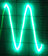 an 3,5 mm jack into the Multi, I measure an resitance of approx. 40 ohms. with an 100 ohm resistor as terminator the signal on the end of the cable looks like that:
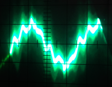
not very reliable....
I wonder why the input resistance of the multi is so low, if the signal the Multi is "seeing" looks like that, no wonder everythings going crazy....
I've ordered a meter ET340 now and I'm hoping it will work....
seems not so accurate...
I think it is an error in the software or the settings
The Multi is always pumping Energy back to the Grid, wich make the Gridmeter rotating backwards...
The Transformer is on the right PHase and in the right direction (mounting it in reverse makes the multi using power from the grid to load the batteries although they are over 80% soc and the PV is delivering 2,5 kw...)
Selecting "no feed in" or "feed in excessive solar charger power" does not alter the behaviour.
I am desperate...
I have a setup similar to the following diagram, and it works correctly to prevent power feedback to the grid. Are you using the ESS Assistant on the Color Control GX?
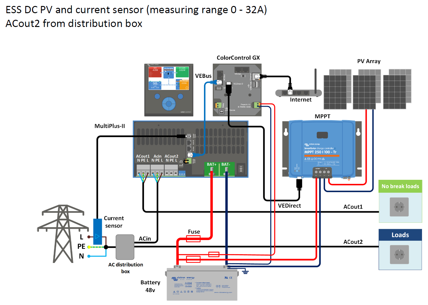
Hello Nigel!
My setup is the same, instead of the Color control GX I use an Octo GX and two MPPT 150/35 and pylontechs. But I think thats marginal. I've installed the ESS Assistant on the Multiplus, so it is shown on the Octo Remote Console.

I've tried a lot, but the Multiplus always starting to feed power into the Grid via AC In.
The current Sensor is placed as shown in Your setup, when I install it 180° reversed (the Arrows showing in direction of the loads), The Multi is pumping energy into the Pylontechs.
Tried a lot of Settings, found a new Firmware today (2628459) today, it looks diefferent in Details on the VE.Config, but always the Multi is pumping power into the grid...
Would be nice to compare your setup and settings!!!!
Hi Udo229
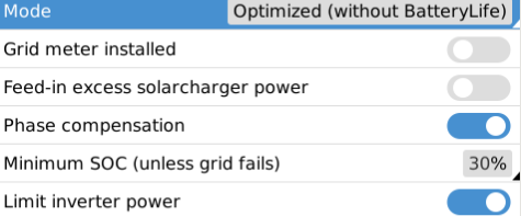
I think the important ESS settings, for your issue, are as follows:
Hello Nigel!
Thanks for your Reply!
I think I tested those settings.
The Actual are like this:


Tomorrow (its night now in europe) I'll try your proposals, but I think I have yet...
Maybe you can download your configuration file via vrm and load it up here?
Then I can open it via VE Configure3 and can try to find a clue in the settings...
Thanks,
Udo
Hi Udo229
Are you sure that the current sensor is correctly clamped around the Live wire of AC_IN? It must not clamp around more than one wire, and the clamp must "click" closed so that the smooth ferrite surfaces are together.
Yes, it‘s clamped around the phase wire coming from the main switch leading to the distribution box. I‘ve been working with electronics and electrotechnical installations for 35 years now. It doesn‘t help against all mistakes, but some.
I‘ve drawn a signal from the transformer via an oscilloscope and measured an dc-resistance of approx. 100ohms trough the transformer.
I‘ve given up the idea of measuring the current to/from the grid via the undocumented transformer solution and I hope my grid-meter will arrive next week. RS-485 should work over 20 meters.....
Can you share / check:
-is Pylontech BMS selected as battery monitor
-what are the parameters sent by the Pylontech BMS (in remote console, devices, pylontech, parameters)
-what are the charge / discharge voltages set in the Multi? (VE Config) and ESS assitant settings? (select the assistant and click 'summary')
-what is the battery voltage
udo229_inst_ttyO5_Interfaces_Mk2_Tunnel(4).jpg
here's my Multi-configuration. It's not a jpg, you have to change the ending in ".rvsc" , the upload refuses "rsvc".....
The settings for the pylontech I've found and copied from the Victron Homepage
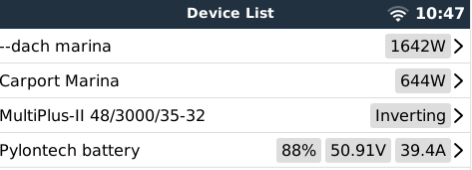
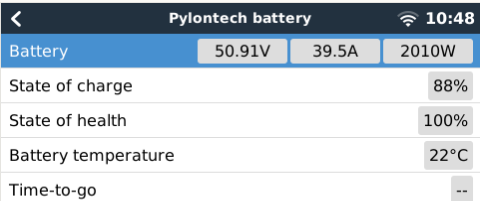
Here the settings of the batterie in the console:

Was this a firmware issue in the end?
NO..i have 2 multiplus II in parallel and i set the grid setpoint between 110-220w(alternate with node red) to avoid feed in. Now i have feed in 0.1kw per day. I dont want this value for the setpoint but I did not find another solution. Too bad because victron doesn't find a solution for multiplus to respond faster when feed in appears.
15 People are following this question.