question

frosty avatar image
frosty asked

Integrating 123/smart bms with victron smart BP and Phoenix smart inverter

Hi, I'm planning to use remote switches to control the on/off function of the smart BP and the smart Phoenix inverter, I'd also like to use the relay on my bms to shut down these components in the event of a fault (high/low voltage and temperature etc) and I'm struggling to find a definitive answer. Can I simply interrupt a 12v signal from the battery to the h terminals with the n/o bms relay to control the shutdown and then connect my remote switches after the relay to control the on/off functions of the BP and inverter?

Thanks in advance

James.


BMSPhoenix InverterBattery Protect
2 |3000

Up to 8 attachments (including images) can be used with a maximum of 190.8 MiB each and 286.6 MiB total.

4 Answers
Paul B avatar image
Paul B answered ·

Hi James Its a bit hard to advise as I dont have a full diagram of your setup nor what model Phoenix you are using etc. but basically using the 123 smart to turn off loads or charge by a BP for each is fine.

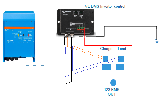
I use the Victron VE BMS unit and connect this to the 123smart units load and charge relays. this unit then connects to the inverter via the ve bus and thus turns the inverter off if required. when a LOW battery voltage is detected by the 123 smart

this way you dont need the BP at all for the Inverter load, however if you do have other loads besides the Inverter then one would still be required for them

you have to be careful with the BP as these unit are NOT bi directional ie one for loads and one for charge is ok, you should not use only one BP unit to turn off both charge and loads.


below is a very ruff diagram note the blue and orange charge and load colors may need to be reversed basically the orange goes open then the charge turns off and the blue goes open the load turns off you can also use the VE bms to turn off the BPs as well (this diagram is for a multiplus or quattro. I have not connected this to the Phoenix myself so TEST first.

(NOTE This is NOT a authorised usage of the VE BMS unit by Victron)


1597564025395.png (73.1 KiB)
2 comments
2 |3000

Up to 8 attachments (including images) can be used with a maximum of 190.8 MiB each and 286.6 MiB total.

frosty avatar image frosty commented ·

Hi Paul, what cables did you use to connect the two bms?

0 Likes 0 ·
jeroend avatar image jeroend frosty commented ·

I do not see how this could possibly work without a signal encode/decoder in-between.

The relays in the 123BMS are simple dry relays (on or off) where the circular connectors on the Victron BMS are, to my knowledge, talking a datastream between the Victron cells and the BMS (in other words: not just a simple on or off, although in the end it comes down to that)

0 Likes 0 ·
Phil Gavin avatar image
Phil Gavin answered ·

This is worth investigating.

The Phoenix ( at least my 5kVA version) is basically a Multiplus without an AC input. It can still charge from AC if it is AC-coupled on its output with a PV inverter. It is also a bi-directional charger, and you can enable the full charger settings in the Veconfig software.

Read up on two-wire BMS control of the Multiplus. I am the other side of the world from my Phoenix right now, but I think the two inputs Aux and Temp are physically available to you on a Phoenix and that full two-signal control is available to you.

Edit: I have just checked that the software assistant is available to you on my Phoenix settings file.

This would be the most elegant solution.

2 |3000

Up to 8 attachments (including images) can be used with a maximum of 190.8 MiB each and 286.6 MiB total.

frosty avatar image
frosty answered ·

Really appreciate your replies guys, I should have also been a little clearer on my design spec.

My inverter is a 3kva Phoenix smart inverter (not multiplus) and I had intended on using a 100a smart battery protect to switch the incoming power supply to my blue sea 12v distributor.

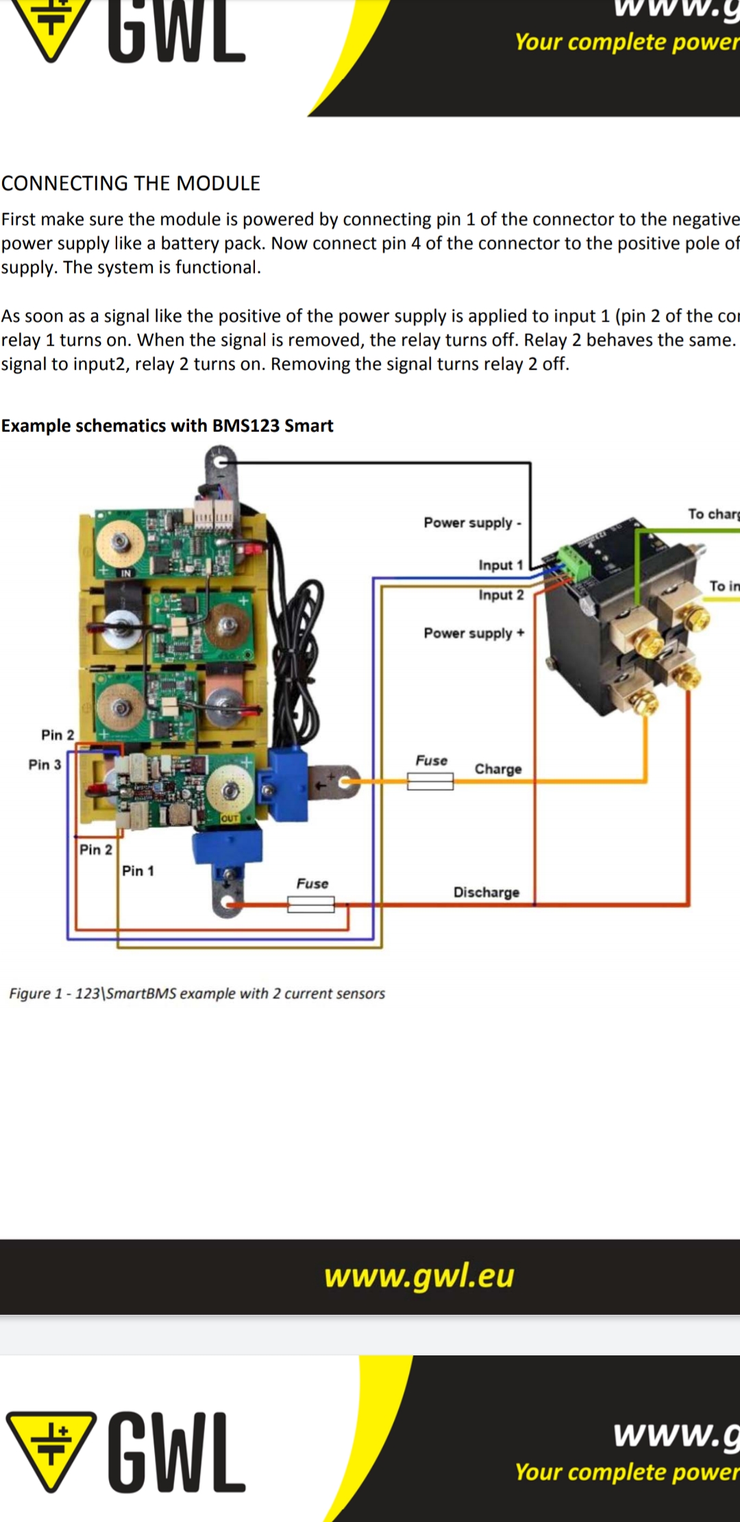
In the photo that I have included it shows the isolating relay being operated buy simply interrupting a positive battery signal with the bms relays, by simply replacing the isolating relay with the h terminal on the inverter and bp would this work in the same way and eliminating the need to use the ve bus bms?

Many thanks in advance for your time


James.


1 comment
2 |3000

Up to 8 attachments (including images) can be used with a maximum of 190.8 MiB each and 286.6 MiB total.

Phil Gavin avatar image Phil Gavin commented ·

Isn't this what you are trying to do? ( just with a BP)

https://diysolarforum.com/resources/victron-two-signal-bms-assistant-for-multiplus-and-quatro-inverter-chargers.61/

What I am saying is I think this will work on a Phoenix as well.

0 Likes 0 ·
frosty avatar image
frosty answered ·

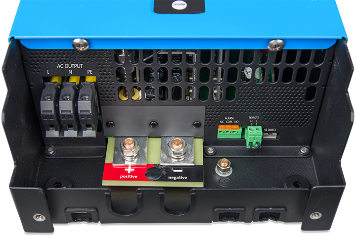
The following photo shows the only inputs I have on my inverter, the link you've provided shows temp sense and auxiliary inputs, have I missed something? I'm very new to this so I apologise if I'm missing something obvious. Would the previous wiring diagram work with this setup?

Regards

James.


4 comments
2 |3000

Up to 8 attachments (including images) can be used with a maximum of 190.8 MiB each and 286.6 MiB total.

Phil Gavin avatar image Phil Gavin commented ·

It would seem you don't have the inputs you need on your model.

Your Phoenix looks quite different to mine ( from memory, anyway).

I am not sure all is lost though, that remote input might work. I am assuming the fact that is bridged it is a remote ON/Off.

0 Likes 0 ·
Show more comments

Related Resources