question

logic28 avatar image
logic28 asked

Multiplus II analog/digital input/output ports

Since the Cerbo GX only has digital inputs I was investigating the potential of using the Multiplus optional connections instead but all I can read from the manual is the following:

4.4.5. Programmable relays

The relays can be programmed for all kinds of applications, for example as a starter relay for a generating set.

4.4.6 Programmable analog/digital input/output ports

These ports can be used for several purposes. One application is communication with the BMS of a lithium-ion battery.

Where can I find more instructions on how to use the digital in/out ports?

Multiplus-II
1 comment
2 |3000

Up to 8 attachments (including images) can be used with a maximum of 190.8 MiB each and 286.6 MiB total.

Alexandra avatar image Alexandra ♦ commented ·

@Logic28

There are no digital inputs on the inverter so is that from the GX manual?

In the GX they are configured and labelled through the menus.

-1 Like -1 ·
3 Answers
sharpener avatar image
sharpener answered ·

The same text above (more or less) appears at 4.1.12 in my Multi II GX manual (3 & 5k size).

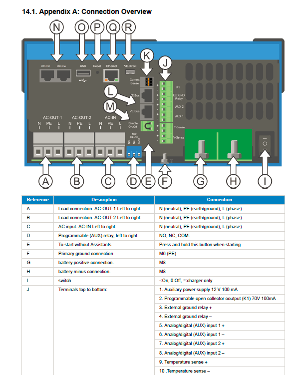
On these models there are an open collector transistor (see terminal strip J below) and an output Aux changeover relay (D below) which I use respectively for driving a warning light and turning off my heat pump if the grid fails.

Also there are 3 Aux inputs (see J below), they can accept analog or digital signals. There is an internal pull-up resistor so the normal state is open (logic high), you can short them to ground to achieve logic low.

1722804994189.png

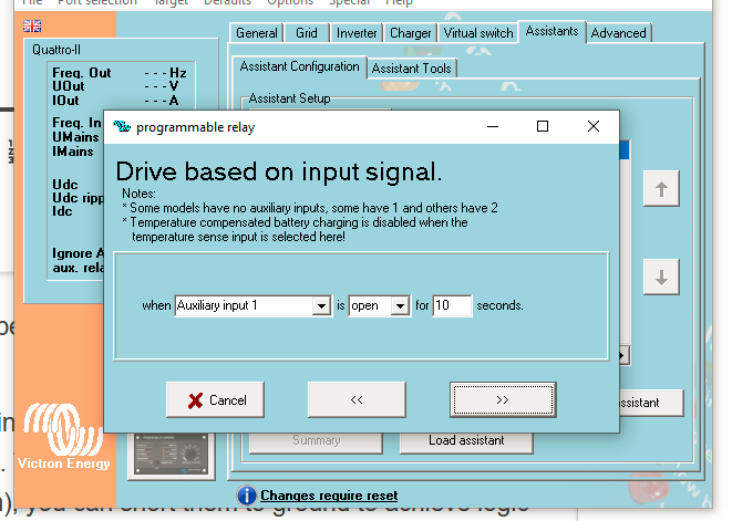
They are used by various Assistants, for example Programmable Relay can use any of the three as on/off


1722803385998.png


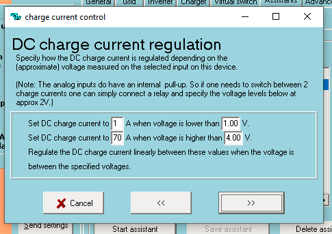
The Charge Current Control Assistant will accept either digital or analogue signals

1722803652523.png


1722803385998.png (53.7 KiB)
1722803652523.png (22.5 KiB)
1722804994189.png (127.3 KiB)
3 comments
2 |3000

Up to 8 attachments (including images) can be used with a maximum of 190.8 MiB each and 286.6 MiB total.

logic28 avatar image logic28 commented ·
My multiplus II is not a GX model but it should have the same arrangement so I will check. Strange though I could not see these images on my digital manual, I shall check the printed version.

Thanks for your comment

0 Likes 0 ·
logic28 avatar image logic28 commented ·
Having said so I see that all digital or analogue connectors are only for inputs in both the Multiplus and Cerbio GX.

I was looking for some outputs that I could use to drive different relays since the Cerbo only has two.


0 Likes 0 ·
bartoff avatar image bartoff logic28 commented ·
AFAIK the only way of control the digital outputs/relays of Multiplus is via SmartSwitch or Assistants. There is no possibility to control them via Cerbo directly. Does not differ between Multiplus-2 GX and normal Multiplus-2 with the exception that the GX board in GX version has NO relays/outputs at all. If you however have MPPT charger you might want to control their relays via NodeRed - you need to set them to "Manual control" in VictronConnect app and after that they are controllable from Cerbo through dbus. Sadly, there seems to be no option in VRM nor Console to control them, but via NodeRed this is at least doable.
0 Likes 0 ·
delf67 avatar image
delf67 answered ·

Terminal 2 on connector J is an output and connector D is a programmable relay.

3 comments
2 |3000

Up to 8 attachments (including images) can be used with a maximum of 190.8 MiB each and 286.6 MiB total.

logic28 avatar image logic28 commented ·
Thanks and sorry, I seem to have missed that, my problem is that I have used the two relays on the Cerbo to start the radial cooling fans of my two MPPTs as they have different temperatures during the daily operation so now I need at least two more "switching devices" (relays or outputs to drive them) for both the generator and for the airconditioning (and possibly the winter heater) for the solar shed.

Alternatively, I'll have to drive the cooling fans with some external temperature device in order to use the Cerbo relays for more important switching.

0 Likes 0 ·
sharpener avatar image sharpener logic28 commented ·

Does your non-GX Multi not still have the aux relay and open collector output mentioned by me and @delf67? That would give you two more output possibilities, the o/c output can be used to drive an external 12 volt relay wired between J1 and J2.

0 Likes 0 ·
logic28 avatar image logic28 sharpener commented ·
Yes it does so I could use the Multiplus Temp Sensor and create a condition for the aux relay or the o/c s1/s2 to drive the Aircon and generator but I probably won't be able to make use of these extra outputs from both of my Miltiplus II since they are running in parallel and I think they would act like one even on the aux connections. Still better than nothing, at least I'll have ways to connect two more switching devices.

It's a shame that Cerbo does not provide four dig/anal outputs as well as inputs in fact it doesn't make much sense having one without the other in my opinion.


0 Likes 0 ·
bartoff avatar image
bartoff answered ·

Having a closer look at your setup I see that you use Cerbo relays to control fans on MPPTs. That is a bit of a waste, since MPPTs have their own relays and they can be set up in VictronConnect to activate when temperature exceeds some threshold. I am not 100% sure however if the temperature is the temperature of the MPPT itself, or shared temperature sense (STS) in DVCC. But there is always a possibility to set them up to manual control and drive through dbus from cerbo, possibly via NodeRed should this be the STS and not MPPT temperature. That way you can get cerbo relays free for better use.

3 comments
2 |3000

Up to 8 attachments (including images) can be used with a maximum of 190.8 MiB each and 286.6 MiB total.

logic28 avatar image logic28 commented ·

I absolutely agree, I've always thought that using the Cerbo relays for that purpose was a bit of a waste but at the time it was quick and functional since the aircon I'd ordered for the solar cabin did not arrive. Now, I'm not aware of the possibility of controlling the fans from the MPPT's internal temperature sensors since they don't have a dedicated digital pinout which is why I wished Cerbo had some so that you could set a condition related to the MPPT's temperature. Unfortunately, I am building my new timber building all on my own and I can hardly afford to spare time for the Victron system, already I've had one of my Seplos 200 10E going on the blink and I cannot do anything about it at the moment since the battery is working nevertheless, just lost all communications and display. During the winter I won't be able to work so much on the 98m2 building so I'll have more time for my system including the assembling of a third battery of 17K. Thanks for the tips


0 Likes 0 ·
bartoff avatar image bartoff logic28 commented ·
If you have os Large have a special look at NodeRed - it allows you to define simple logic of controlling mppt relays and can take any combination of sources to consider. The Problem is that classical MPPT Chargers do not seem to have built-in temperatore sensor and you would have to use external one.

On the other hand - why do switch on/off the fan based on temperature? Maybe just drive the relay time based or keep permanently wired and do not use relays at all? (that would be actually the simplest solution, as the relay cannot get too cold just by fan)

0 Likes 0 ·
Show more comments