Voltage is 52V at the batteires but only 38V at the Victron Multi input. The 35mm2 cable should be big enough but it's old, maybe corroded (?), could that cause this?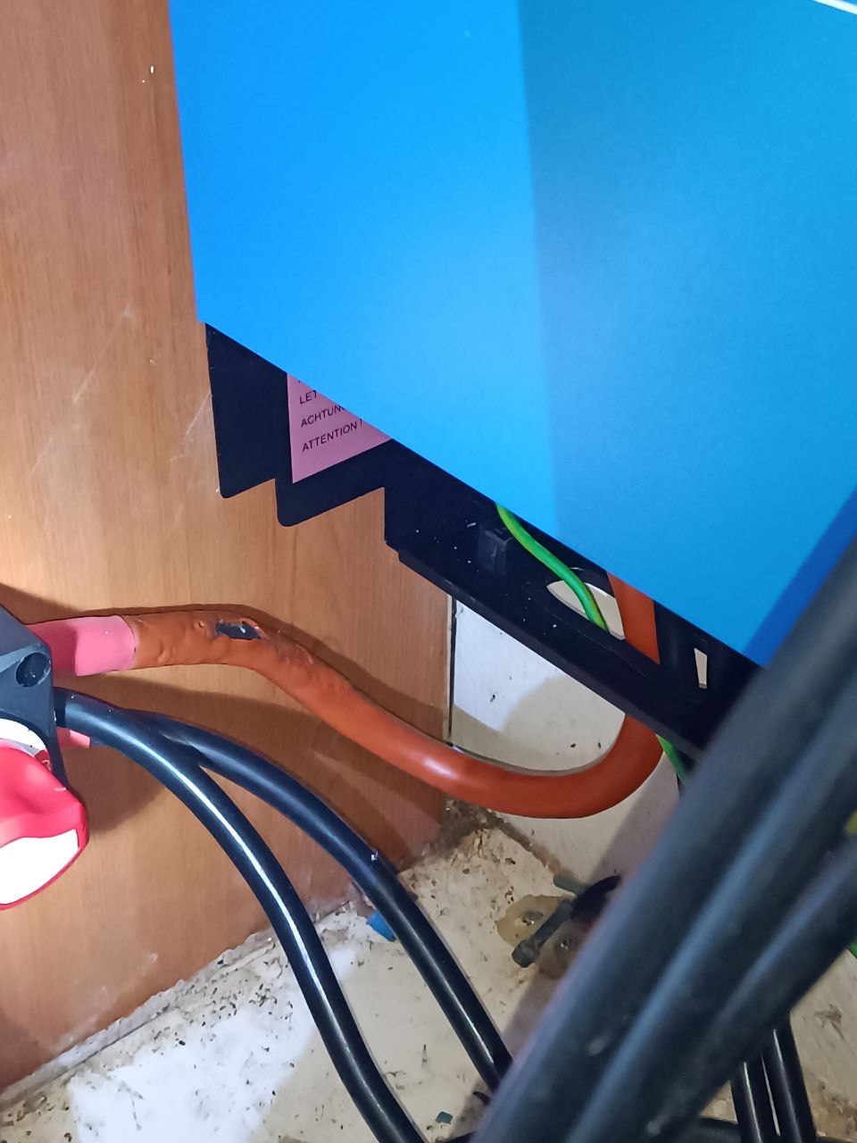
- Home
- Anonymous
- Sign in
- Create
- Spaces
- Grafana
- Node-Red
- Unsupported topics
- Questions & Answers
- Modifications
- Communauté francophone
- Deutschsprachiger Bereich
- Preguntas en Español
- Explore
- Topics
- Questions
- Ideas
- Articles
- Badges
question
What happened to this cable?
Hard to tell by simply looking at a photo but it appears there might have been a sharp kink made in the cable or pinched somehow possibly breaking several strands causing the wire to get very hot at that point and melting the jacket. Don't know for sure but just a guess on my part.
Yes, completely agree I have seen a lot of this in my servicing life.
But also suspect this cable might have been (fatigue) bent a few times in the area of damage causing work hardening, happens in wires just as it does in metal strips, this in turn will cause a higher resistance causing a heat build-up in that area.
It's a fire risk. Replace asap.
It's not clear what the the other black wires are, but a big stack inside the switch may have resistance issues. Better to use a busbar.
If you regularly use the rotary switch, especially under load, you may have damaged the contacts through arcing. Best to check its resistance and replace if necessary.
@Ian0 and @regman54 and. @kevgermany definitely have valid points.
The black underneath should be the second insulation level. If it isn't then that corrosion is really bad and then the cable is wrong.for the application.
Several things to note.
Cable was hot very (obviously). But should have been able to handle the heat if it was an up to standard cable. Causes of heat - bad torque, poor crimp (under crimped) or over crimp so the cable actually became smaller than the recommended 35mm².
The other cause is not using fine strand wire. (Standards again)
If it split there, it could have been damaged insulation damaged during handling and install. Or the cable is not actually up to specifications especially the heat rating (which is very likely the insulation should handle 100s of degrees before smoke) and use of actual copper.
If the corrosion is that bad, then it probably started as a compromised/poorly stored cable. Which means it should not have been installed in the first place. The other thing I have seen on cheaper cable is it is not actually copper... So check that too.
If you have to stack lugs, put the one with the highest power first on, then the others.
Then put a washer on and a springwasher (or however this is called in english) and then the nut.
But as @Alexandra mentioned, for security reason use a Busbar.
However, PVC cables starting to give up at 60°C and are gone at 80°C.
Better is the use of welding cables H01N2-D (do not use the -E, because they are much more flexible of finest strands, but if you do not have the right tools, you endup in a nightmare)
In addition to the excellent points already made, I'll add that the rotary switch you're using isn't rated to the system voltage you're using it on... No readily-available rotary switches are rated to 58-60V as required for a 48v nominal system.
In the Victron manual for the 275A rotary switch it says "The Battery Switch ON/OFF 275A is suitable for battery systems up to 48V." This suggests to me that it's suitable for use on a 48V nominal system so how sure are you that this is not the case? Perhaps I've missed a thread on this topic elsewhere. It does also say in the manual that the cables need to be 120mm to meet the battery switch current rating for what it's worth.
In any case, I think I'll be looking for another means of isolation unless I can get my Victron switch to run a bit cooler than 70C at a continuous 100A load.
Edit: Sorry Justin, I just found the thread where I more or less asked you the same question back in May of this year. I must be having a senior moment! ;)
I suspect that as long as it was never switched under load then it would probably be fine, but of course it's unwise to design a system around that sort of assumption, so I always caution against it. I know that rotary switches rated to 60vDC and up to 300A do exist in the world, but finding one from a reputable manufacturer and less than several hundred USD has proven -so far- impossible, thus the appeal of mechanical relays like the BS-7700 & BS-7716, or breakers like MidNite Solar's MNEDC range.
Yeah, I agree.
I've actually got three of these Victron 275A switches, the first one bought direct from my Victron dealer and the other two bought from Amazon. I bought the second two on impulse but later decided to pursue the Lynx Power-In/Distributor route where my batteries do not have individual isolators. I'm very aware of the reputation of Amazon for fakes but having inspected these switches very carefully side by side, I can't find any differences from the one I got from my dealer. Even the plastic moulding flaws match up. This is the Amazon link ( https://www.amazon.co.uk/gp/product/B095X94JXF/ )
Anyway, my original dealer supplied switch had been used from day 1 and that was before I learned the proper sequence for soft start power up of my Pylontech batteries. So I certainly DID cause an arc on at least two occasions with my original switch during power up. So when I installed my Lynx bus bars, I inspected the switch and found carbonisation of the contacts and dielectric grease. As a result, I replaced the original switch with one of the Amazon switches and that's what I have been running since then.
I don't think I have ever operated this new switch while under load or without using soft start but recently I found it was running at 70C under a sustained 100A load. So, my intention is to check connection torque then remove the switch and inspect it for signs of carbonisation. I have a brand new switch which I can use if there are signs of carbonisation.
I too have one of the victron switches and I’m recording just two degrees over the neg terminal which is more or less always at ambient temp, someone on here told me to build a precharge circuit into my system for battery connection. Although not needed on the Pylontech I still do it this way not sure but makes me feel at ease lol
Yeah it does heat up 70amps for three hours gets me 22degrees over the three hours, with the negigive terminal only rising to 15 degrees an hour into those three hours and the ambient temp in the garage went up an hour after the first hour of the three hours of charge to 13 degrees, I’m not charging at 100Amps yet once I get the other pylon I’ll up it 25amps again. Yeah I image its going to get hotter bigger numbers as my old tutor would say more logs going down the same diameter river always loved that analogy.
@Craig Chamberlain are you mesuring before and after the swtich ie from the lynx to the switch and the switch to the multi?just to see if there is any difference over the switch?
I found similar results to you when pushing 100A or more (my 4 hour Octopus Go means I really need to push the amps in when I can) through these rotary switches. I taped a DS18B20 to the cable just a few cm away from the switch and saw it measuring 70c.
Ultimately I think most of these rotary switches just aren't very good, no matter the brand. There isn't a lot of good surface contact area inside, so I eventually ripped all my rotary switches out and replaced them with NH00 fused disconnects with 160A fuses in. Bimble Solar sell them and they're not too unreasonably priced. Replacement fuses are about £5. I *think* they might be sand-filled fuses too so they're good for arc-quenching but I've not opened one.
I feel a lot more confident in yanking these open under load if I need to (there's a good separation once you pull the handle) than I would turning a rotary switch that may or may not be rated for the real 50V+ in the system.
I had considered the NH00 fused disconnect but I don't really want another fuse inline with the one in my Lynx Distributor . Also, the Multiplus-II 5kVA requires a 200A fuse so the 160A NH00 isn't quite to spec. I know it's not a safety issue but might lead to nuisance tripping when running in island mode with a temporary overload.
I'm not too concerned about the question of whether the rotary isolator is rated to 58V or just 48V and my batteries never exceed 52.3V anyway. In fact they spend most of each day below 50V. The only thing that bothers me is the heat which I'll try to resolve later this evening.
Thanks for your comments though - good to know it's not just me! :)
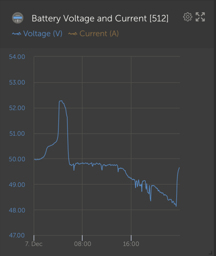
I do have a thermocouple which I could tape on to the cables to get a more accurate figure.
Yeah got me looking at the NH to there are different units with higher amp rating, like you the volts don’t trouble me, it’s the amps that are causing the heat. What about on the Lynx as if the heat is near enough to the switch temp then I don’t think the switch is an issue
I was told on this forum that this switch is "of course" compatible with 48V systems. Also Victron writes that this switch is for up to 48V systems. Victron also use this switch in their Multi RS drawing with 2 x 25.6V batteries. Why would Victron recommend this switch for the Multi RS if it is actually max 48V?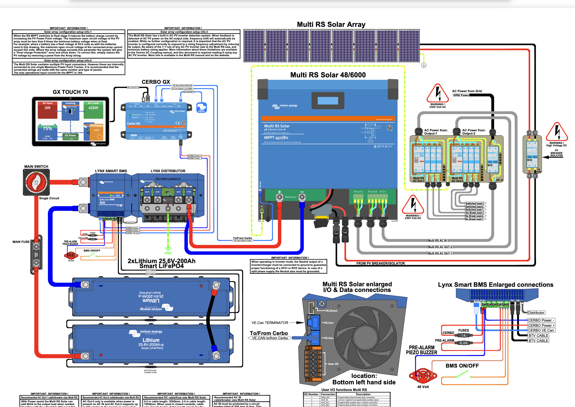
100% heat damage and it doesn’t look like it’s started from the switch bubbling on the cable or sleeving if that is sleeving, if not I would say the connection to your multi isn’t great as the heat has generated at that end hence bubbling multi end and the discolouration of the insulation that’s if it is not sleeved!
What multiple are you running?
The heat definitely, IMHO, came from the switch end.
I'm very interested in seeing the cable sawed in halves, to see wether it is copper-clad or real copper.
is it possible to know wether it was new for this application, or was this normal cable used before (wrongly) in a cable-chain and ended months later in the trash-box. After that it was picked up and misused/reused again. Mechanical dead, overburdend with heat by lug stacking. Maybe 10 iD lug on 8mm oD screw above smaller ones from the black cables.
Thanks for the replies! I didn't get any email confirmation for the replies, so didn't see all the replies until now.
The cable was an older cable that the installer said was ok. I checked it now and it is brittle and make cracking sounds when I twist it, so I guess this cable is not very good. Also the connection to the Multi was small and poor and looks black. I think it started happening when we connected to shore power for the first time recently, and got around 5000W in together with solar at the max. I'd set max charging to 100A.
I've already replaced this cable, and will also look over all the other cables (and will also avoid charging at 5000W which I don't really need to).
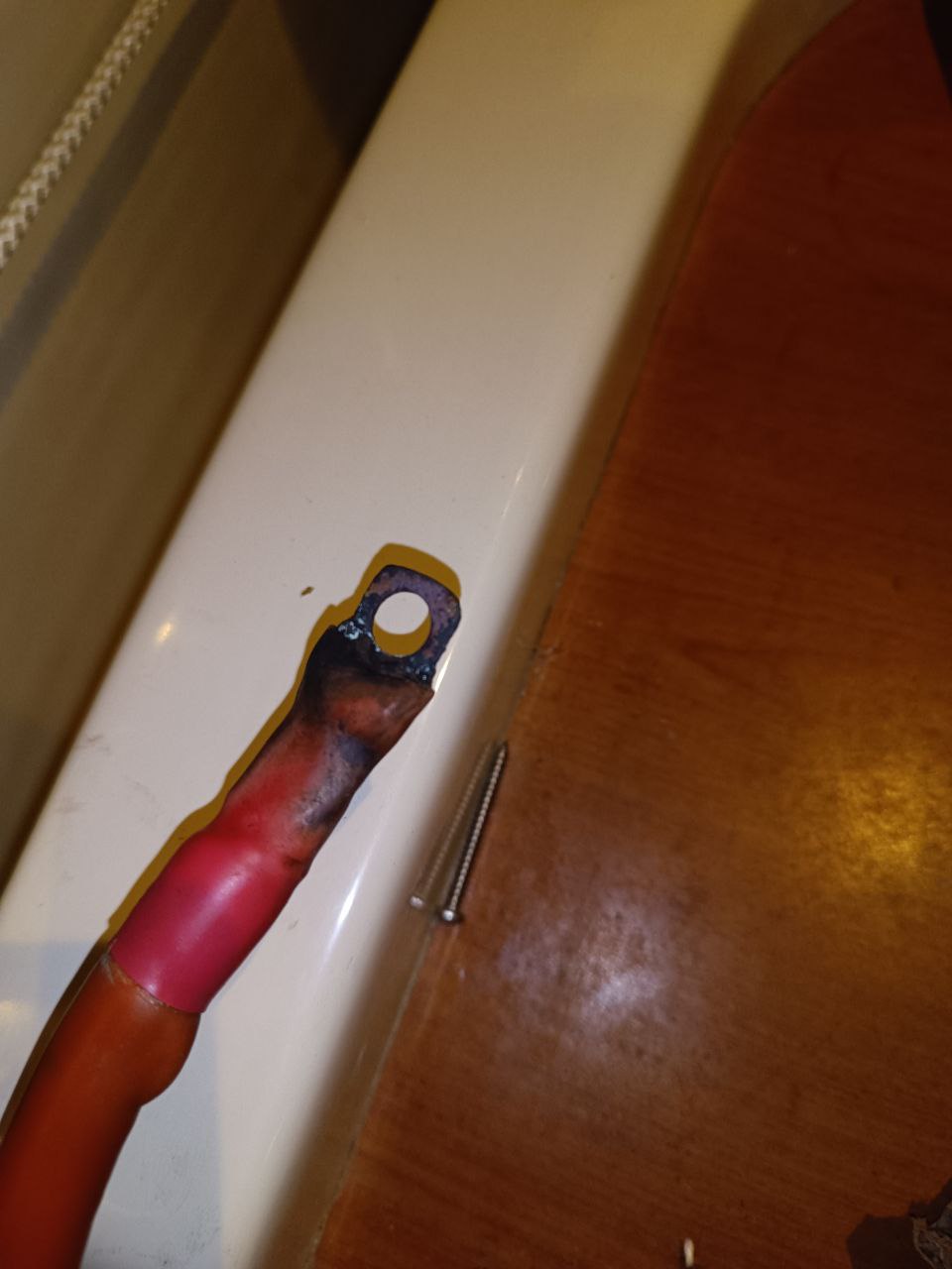
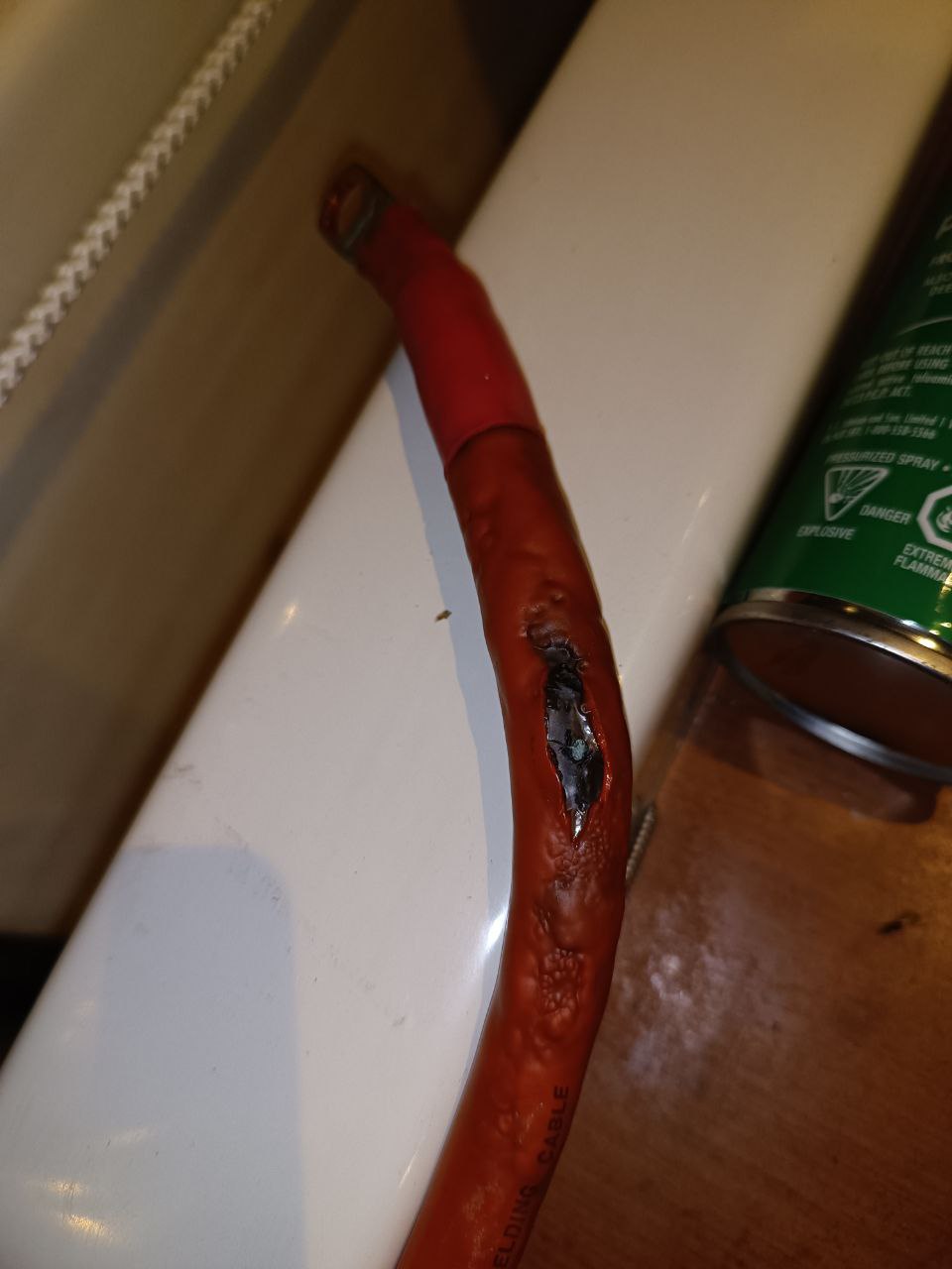
If you haven’t replaced the switch at least i hope you cleaned the contacts don’t answer my previous question as you answered here. Still IMO I would worry about the volts it’s the amps but the lug looks like it hasn’t got any meat on it to me which would 100% cause buildup of heat which just leads to more resistance and heat until this happens. Is the cable copper clad and by any chance was that lug soldered? As I would say they are looking like the cause as I see what looks like solder in the cable and on the edge of the lug. Is this the case @nick5000
Spot on to everyone that said switch end, I stand corrected Sir’s ;)
It would be a good idea to keep a close eye on temperatures until you're happy the problem is fixed. That switch is clearly suspect.
Related Resources
question details
48 People are following this question.
