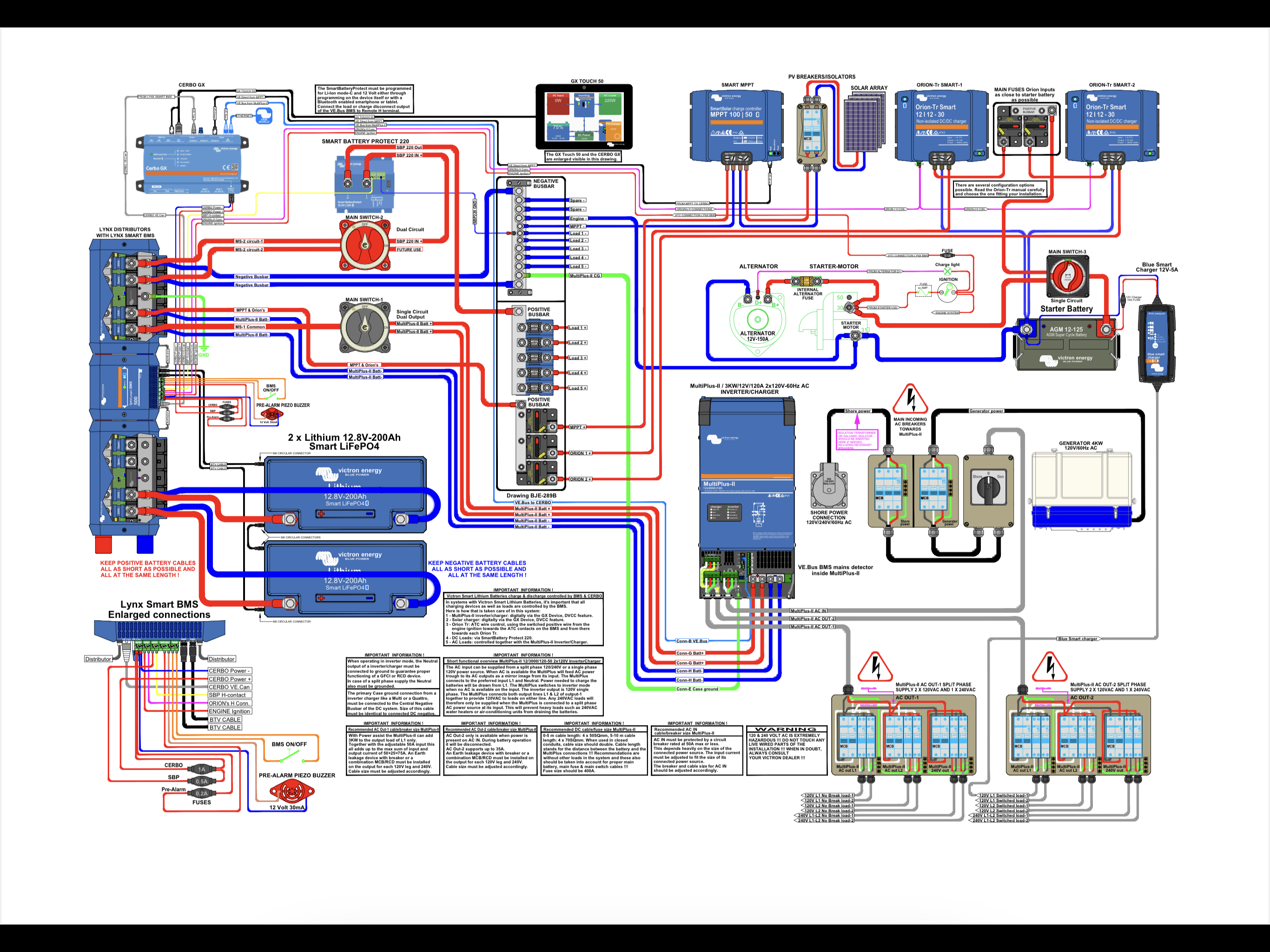
In this circuit diagram, what gauge cable does the green wire marked “GND” from the Linx distributer need to be relative to the various other cables?
Also, why?

This site is now in read-only archive mode. Please move all discussion, and create a new account at the new Victron Community site.
In this circuit diagram, what gauge cable does the green wire marked “GND” from the Linx distributer need to be relative to the various other cables?
Also, why?

It has to be the equal to or larger than current conductors as it has to be able to carry the full fault current of the system as far as I understand.
So equal or thicker than the battery cables to the Lynx BMS?
I‘m confused as to why that would be necessary. The full fault current is surely only in the battery circuit, and with fuses everywhere, what are we trying to achieve by also giving that path to ground?
If I run a cable from an isolated battery positive terminal direct to earth, nothing will happen so what is the advantage of lining the negative to earth with such a large cable?
I find DC earthing very confusing…
So do I. And regulations also govern alot of it. And those are as clear as mud as well.
It needs to big enough to blow fuses or trigger safety devices.
Mobile or fixed install also changes things.
Some batteries are negative grounded.
Sometimes only the case of the battery.
Some systems are not grounded at all.
Lynx manual 6.2.3
Would be interesting to know officially
Lynx Shunt VE.Can product page
Additional resources still need to be added for this topic
31 People are following this question.