question

Jim avatar image
Jim asked

Cerbo GX Active Relay Output Has Zero Volts

I have a temperature sensor plugged into my Cerbo GX. The GX recognizes the sensor and reports the correct temperature. I set the temperature sensor to turn on relay #1 based on a temperature threshold. That works as the readout on the Touch 50 says that the relay is "Active". I also tried it with relay #2 and it also goes active. I can hear the relay click on.

However, I'm not seeing any voltage produced by either relay. I have a small 12v computer fan that draws less than .3 amps and it won't turn on. This is on a 12 volt system that includes a Multiplus 12/3000, two MPPT 100/50, BMV-712 and a Battery Protect 65. I've tried a lot of things to troubleshoot.

1. Switch pos/neg wires

2. Switch between NO and NC

3. Press the ferrules in as far as possible

4. Check with a voltmeter both with and without the plug that the ferrules are inserted into

5. Tested the ferrules by touching them to my common bus bars and the fan comes on just fine.

6. Upgraded the Cerbo GX firmware to the latest version

I'm pretty new to the Cerbo GX, so maybe I misunderstood how this should work.

Is there a minimum length that the ferrules have to be in order to make contact with the Cerbo GX relay pins? I don't think this is the problem because the voltmeter showed no voltage on the pins without the plug installed.

cerbo gxRelay
2 |3000

Up to 8 attachments (including images) can be used with a maximum of 190.8 MiB each and 286.6 MiB total.

6 Answers
Guy Stewart (Victron Community Manager) avatar image
Guy Stewart (Victron Community Manager) answered ·

Hi @Jim,

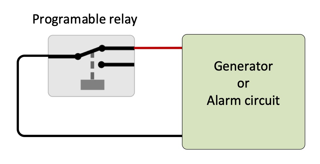
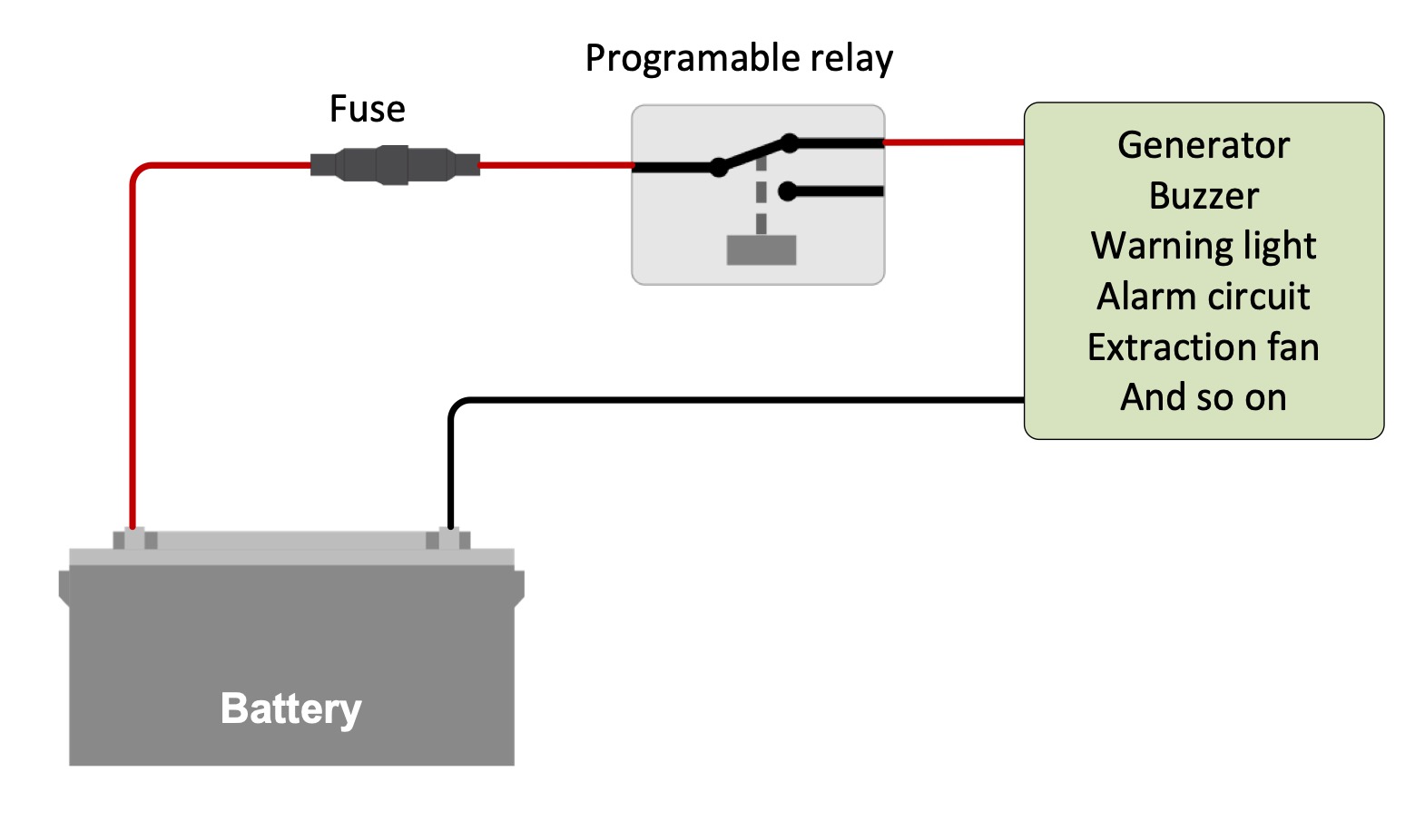
The relay is just a switch, it does not provide voltage. This is called "potential free".

You will need to pass through a voltage from somewhere else on the circuit through the relay.

cleanshot-2022-05-31-at-103508.jpg


Some applications such as a generator autostart do not require a voltage, just that the switch is open or closed.

cleanshot-2022-05-31-at-104109.jpg

Your fan will require voltage to be provided though.

Though it is not specific to the Cerbo GX relays - you might be interested in this online training that also discusses this in general terms - the diagrams above were taken from the linked PDF presentation - https://professional.victronenergy.com/online-training/16/

You will need to create a free account to access it.


1 comment
2 |3000

Up to 8 attachments (including images) can be used with a maximum of 190.8 MiB each and 286.6 MiB total.

Juraj Nikolov avatar image Juraj Nikolov commented ·

@Guy Stewart (Victron Community Manager)

Hi,


if I have 48V system, can I use this battery voltage 44~57 voltage, for powering the relay coil, which would switch, e.g. generator?

Connection should be ?: battery voltage on COM, from the NO/NC of the 1coil pin, from 2coil pin the relay and that would be 230 voltage.

better on pincture :)


Main question witch voltage can handle this relays on GX ?


Thanks


1661269452961.png

0 Likes 0 ·
1661269452961.png (182.2 KiB)
Jim avatar image
Jim answered ·

Thanks! That makes a lot more sense. I should have checked for continuity with and without the relay closed. I have thermostats for my battery warming system that work like you describe, but it's summer so it didn't occur to me.

2 |3000

Up to 8 attachments (including images) can be used with a maximum of 190.8 MiB each and 286.6 MiB total.

t3z-gb avatar image
t3z-gb answered ·

Hello Jim,

Iv literally been through the same process today, however I connected the fan positive to NO and the negative to NC, obviously Iv failed at getting this to work.

can I assume by your text and the answered that on the NO you have a 12v positive feed, and on the NC the positive feed to the fan, then when the temperature is reached the relay switched to NC and the fan cones on? If this is incorrect could you please explain how you have accomplished this.

thanks.

2 comments
2 |3000

Up to 8 attachments (including images) can be used with a maximum of 190.8 MiB each and 286.6 MiB total.

wkirby avatar image wkirby ♦♦ commented ·
Put your 12V positive feed on the COM (common) terminal. Then the positive wire to the fan goes on the NO (Normally Open) contact. Then the relay is activated then the NO contact will close and switch the fan on.
0 Likes 0 ·
Show more comments
Jim avatar image
Jim answered ·

My recollection is that I ran a fused cable from my positive common bus bar to the center terminal. The NO terminal (left one as I recall) then goes to my fan. The negative cable goes from the negative common bus bar to the fan.

I have three fans. Two 70mm fans are on the same relay. A 120mm fan is on the other relay. They're working correctly. Getting the temperatures and ranges set right are my only challenges right now.

2 |3000

Up to 8 attachments (including images) can be used with a maximum of 190.8 MiB each and 286.6 MiB total.

machany-justin avatar image
machany-justin answered ·

I went through the same same procedure today, but I connected the fan's positive and negative poles to NO and NC instead. Obviously, I was unable to make this work.octordle

1 comment
2 |3000

Up to 8 attachments (including images) can be used with a maximum of 190.8 MiB each and 286.6 MiB total.

Jim avatar image Jim commented ·
That's about what I did that prompted me starting this thread.
0 Likes 0 ·
Pablo Noever avatar image
Pablo Noever answered ·

Does anyone know, how much amps I can run through these relays?

1 comment
2 |3000

Up to 8 attachments (including images) can be used with a maximum of 190.8 MiB each and 286.6 MiB total.

Jim avatar image Jim commented ·

6 amps. The answer isn't in the manual or the datasheet. :( You'll find the answer in the Victron GX product range document.

0 Likes 0 ·

Related Resources