ello guys,
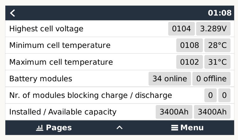
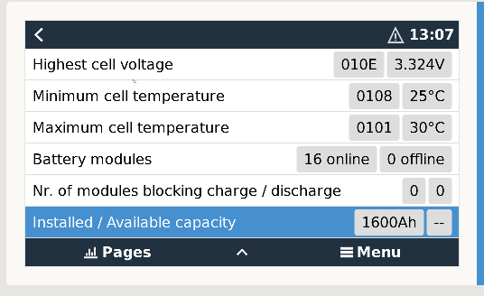
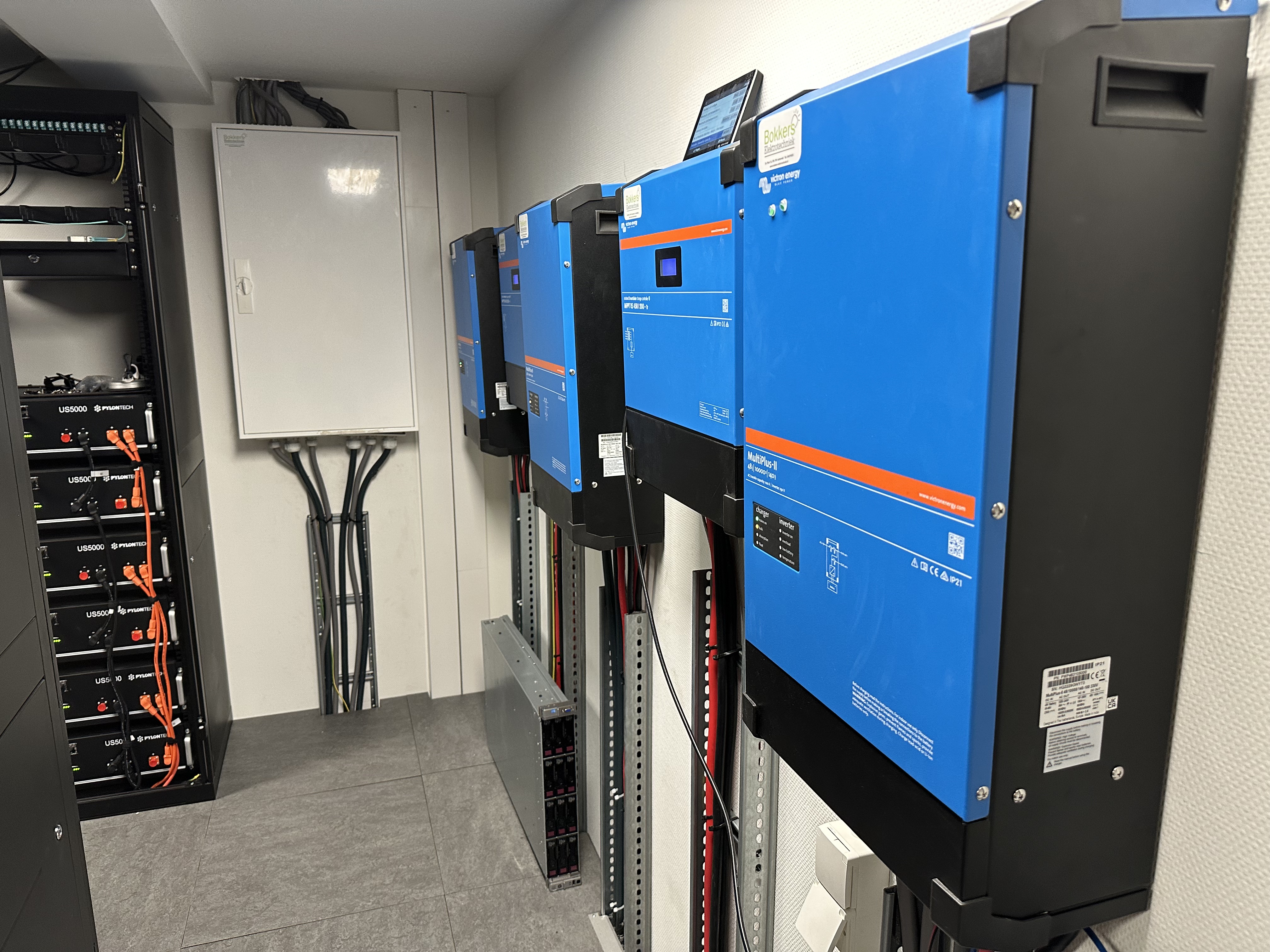
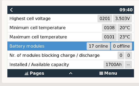
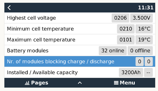
Given the difficulty of correctly configuring an LV HUB with GX and several clusters of US2000C/3000C, I thought it would be good to lay out our parameters that have been successfull with our Victron systems, after many trials and tribulations. LV HUB manual lacks clarity.
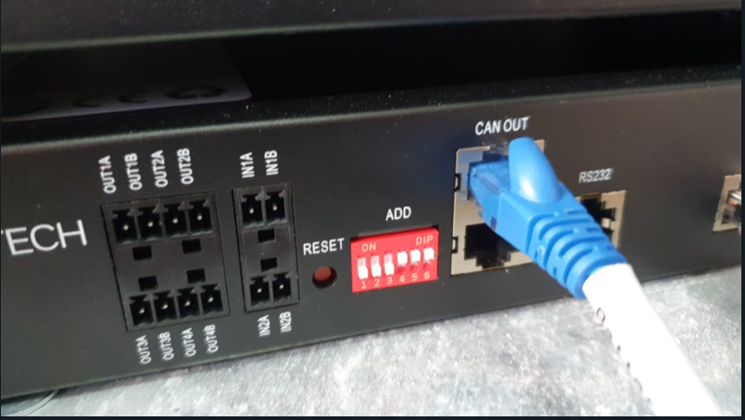
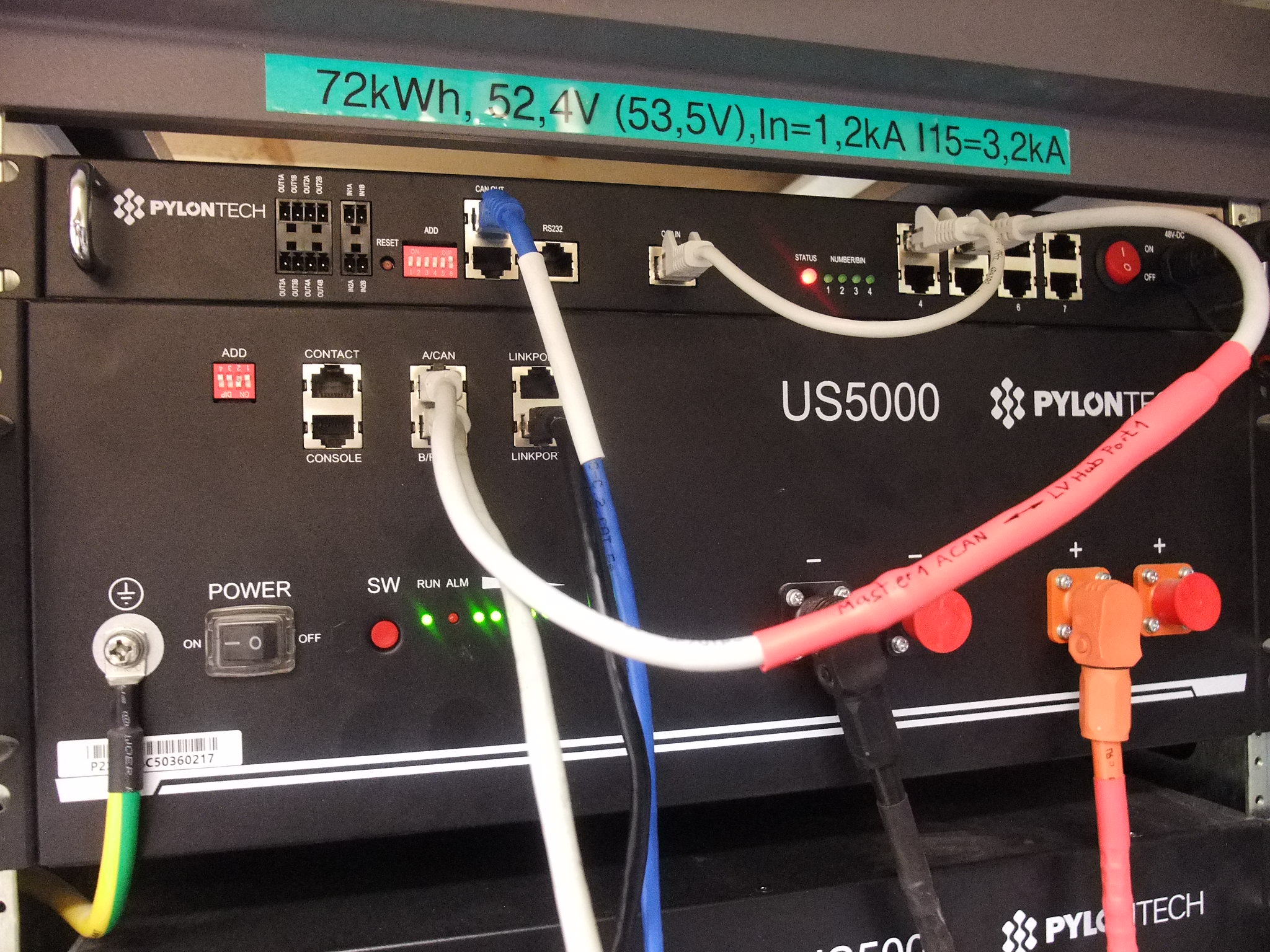
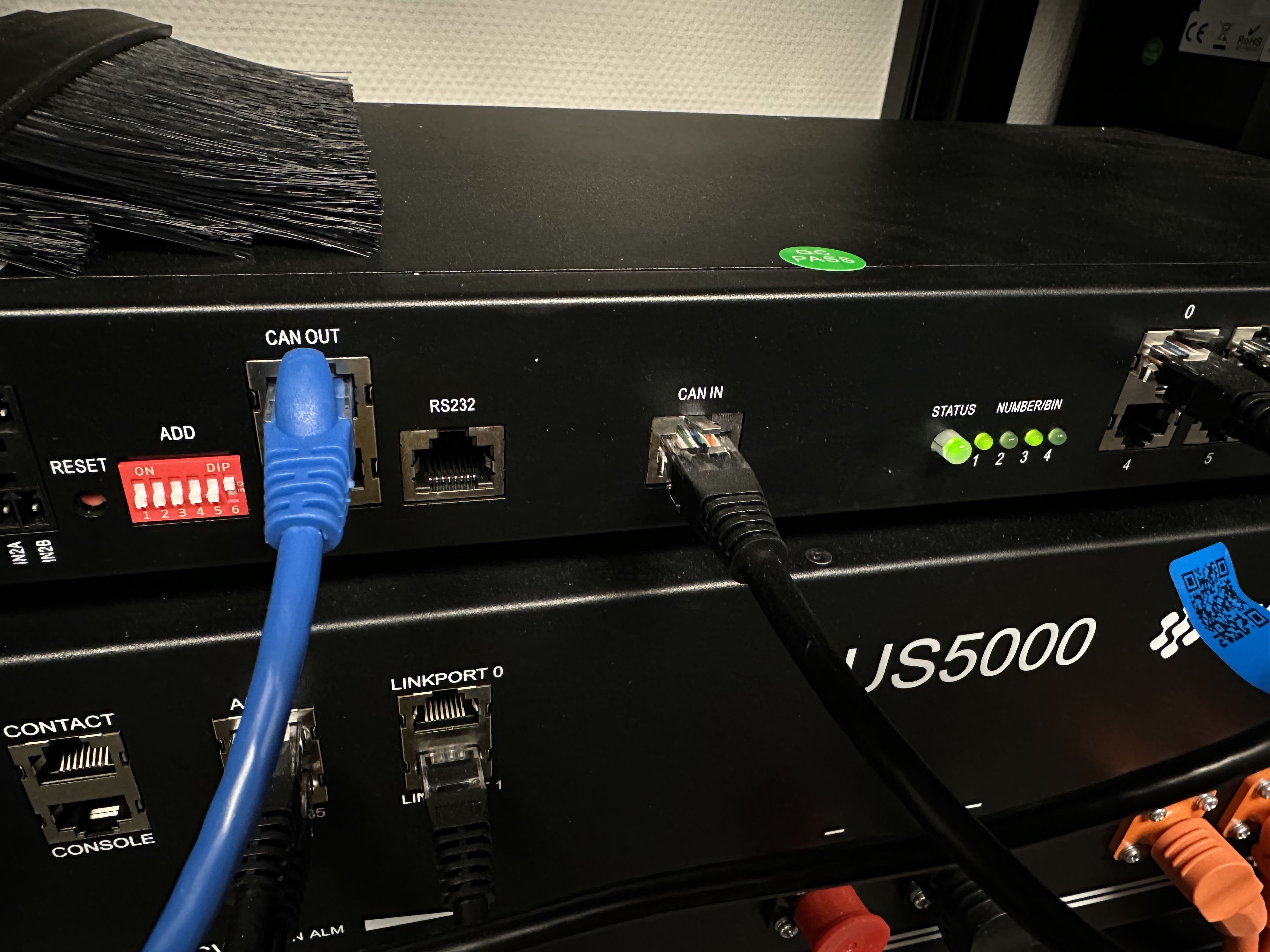
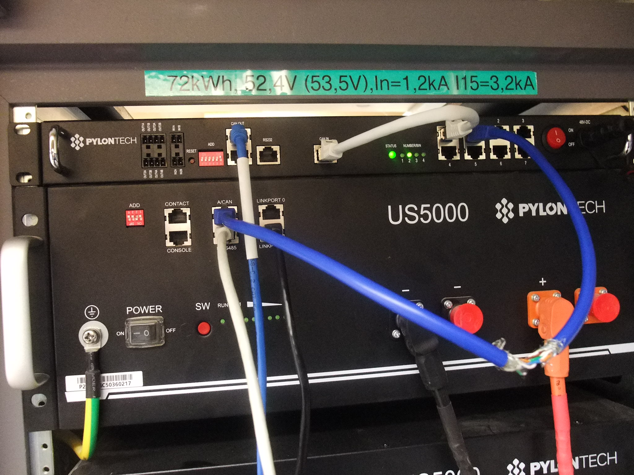
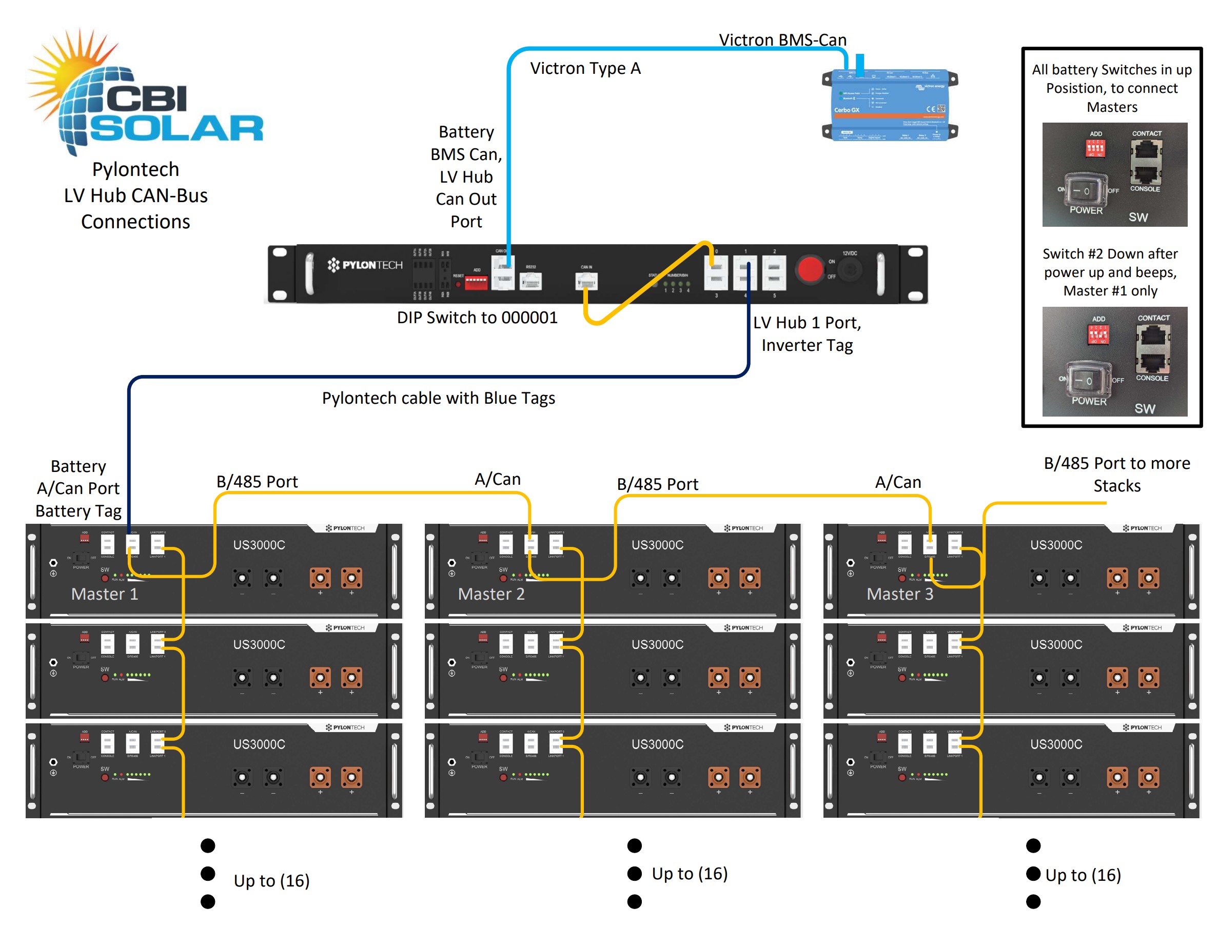
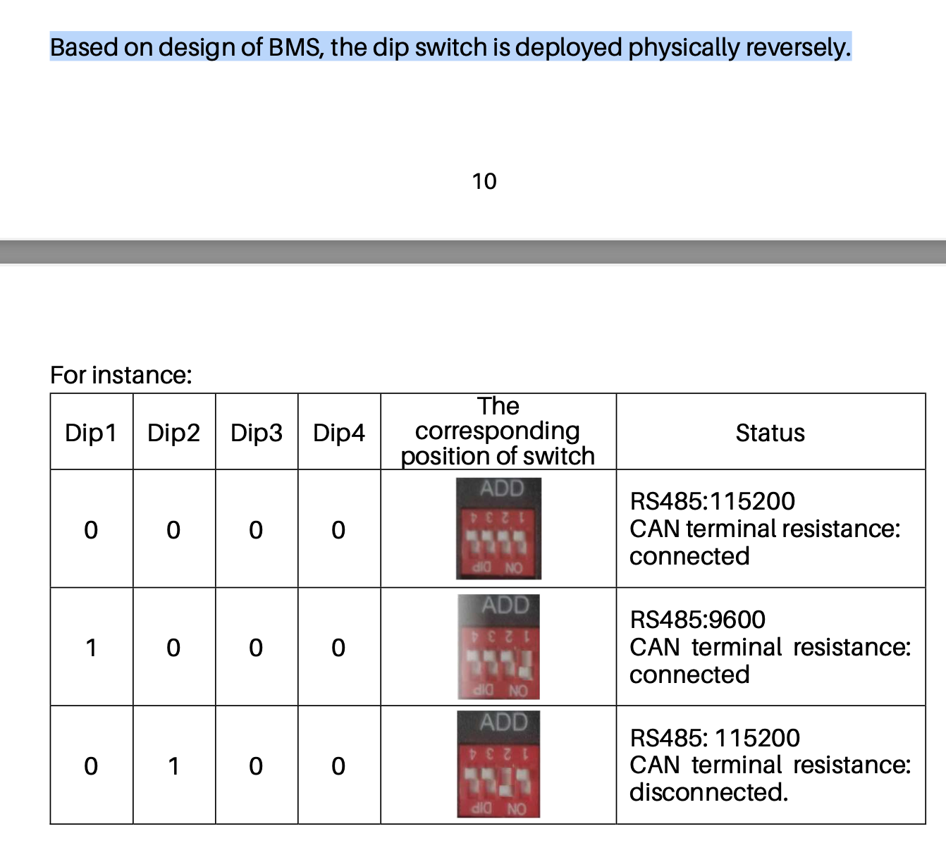
- VERY IMPORTANT : Adress of the LV HUB must be : 000111 (not shown in any Pylontech manual !)
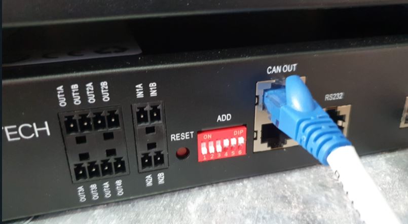
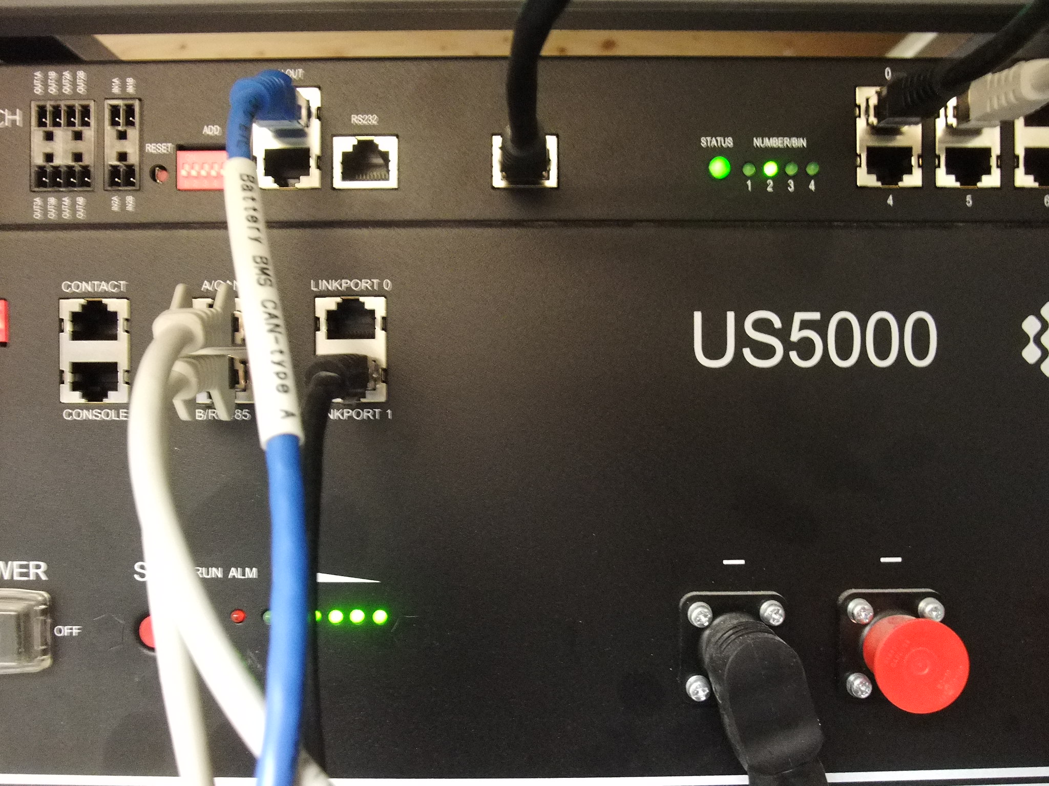
- Cable used : Victron Type A (from "CAN OUT LV HUB to GX).
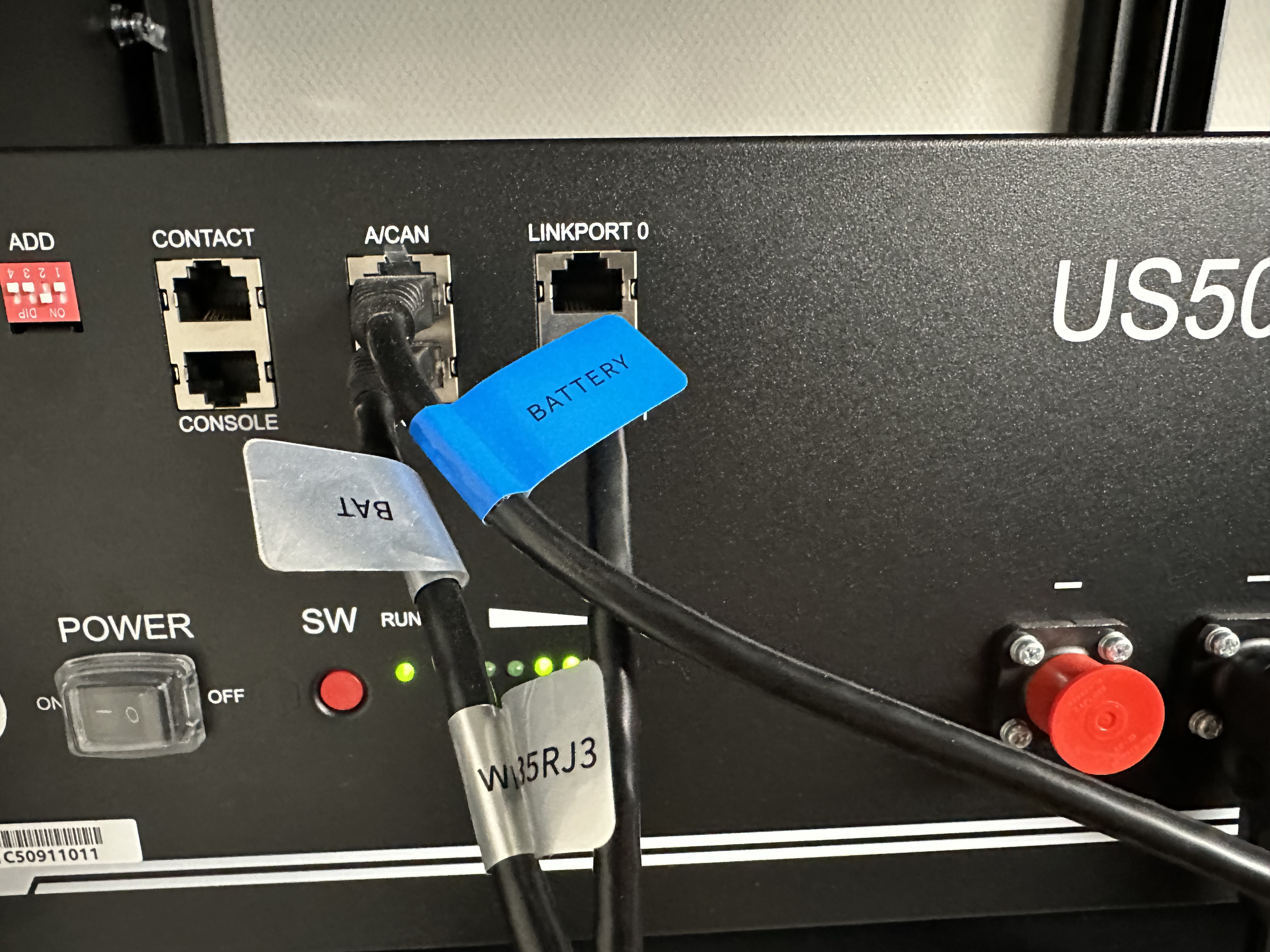
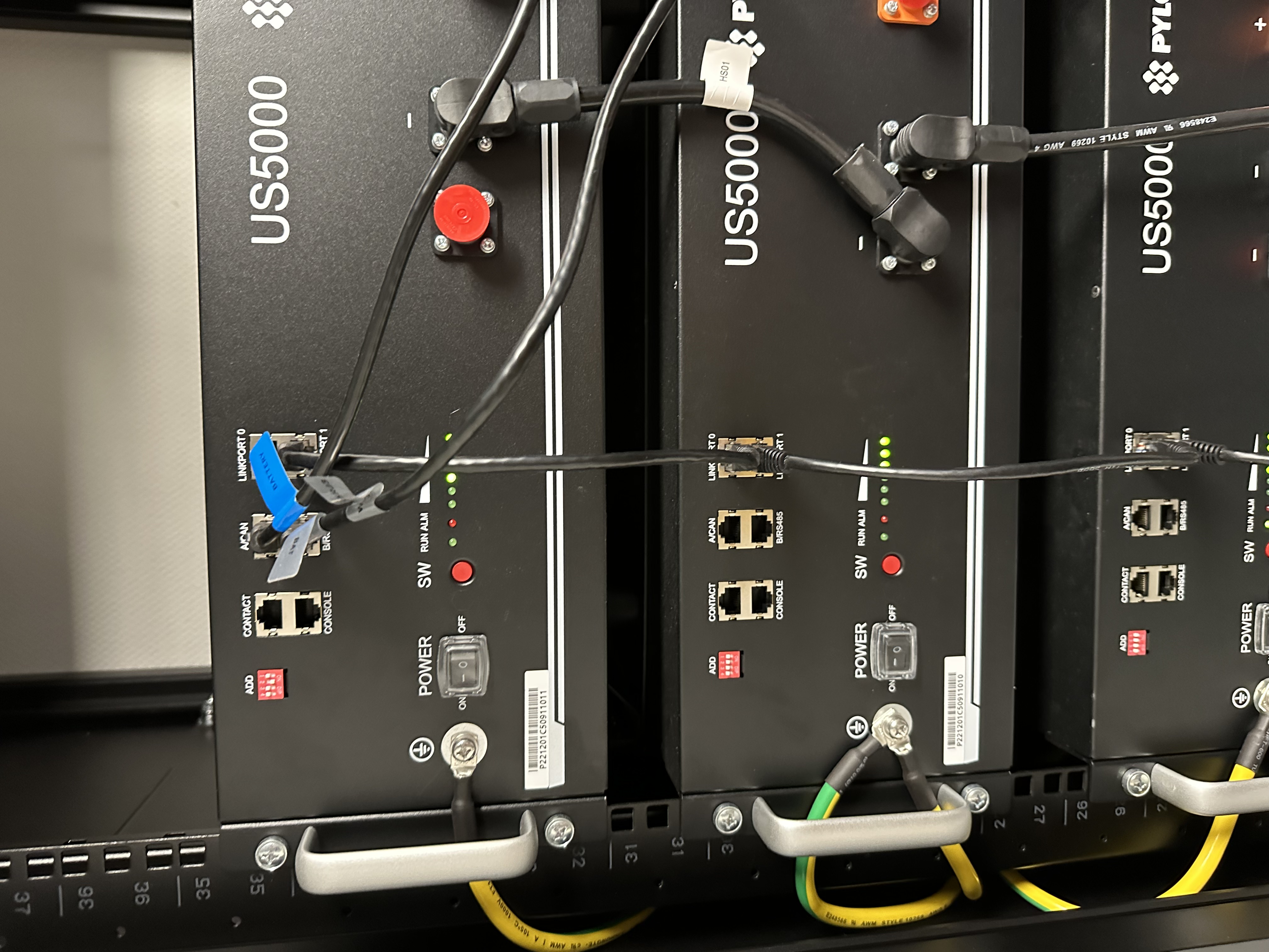
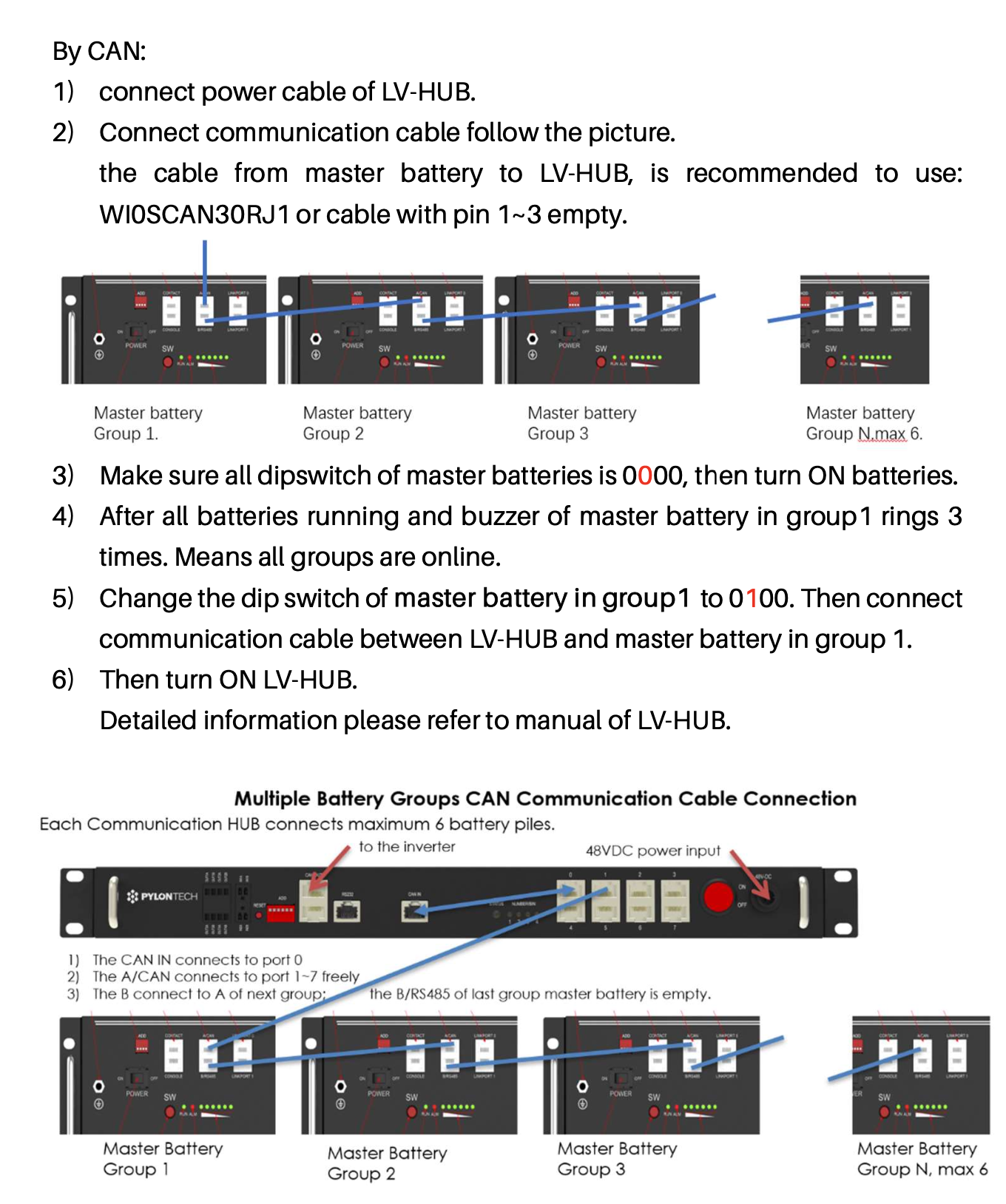
- Cable used to connect Master US3000C battery (group 1) to the LV HUB port "1" : specific cable supplied by Pylontech (PIN 1/3 : null), with blue tag on it.
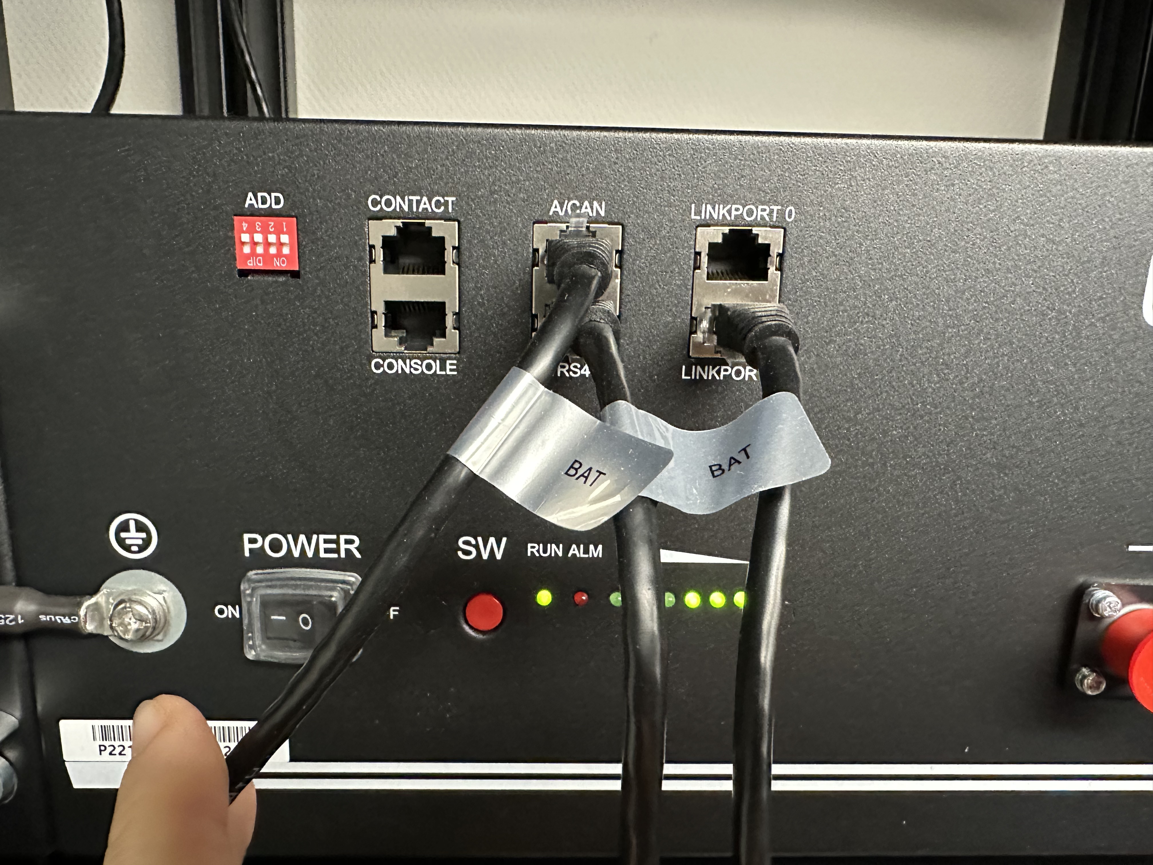
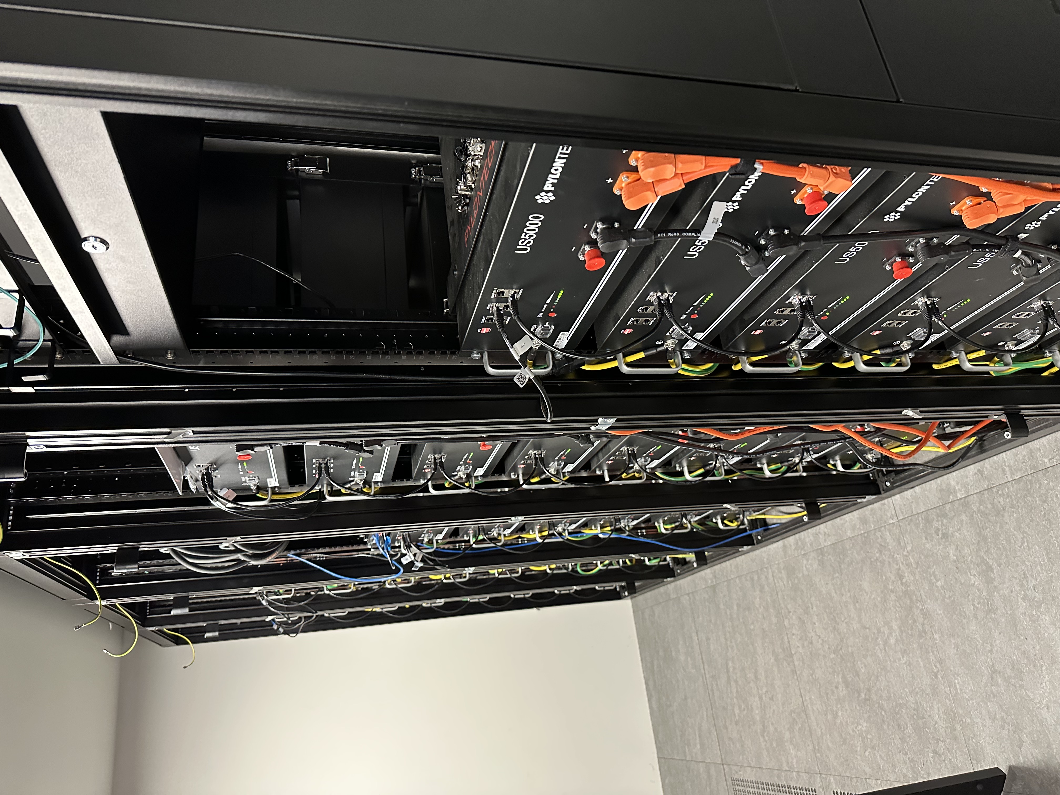
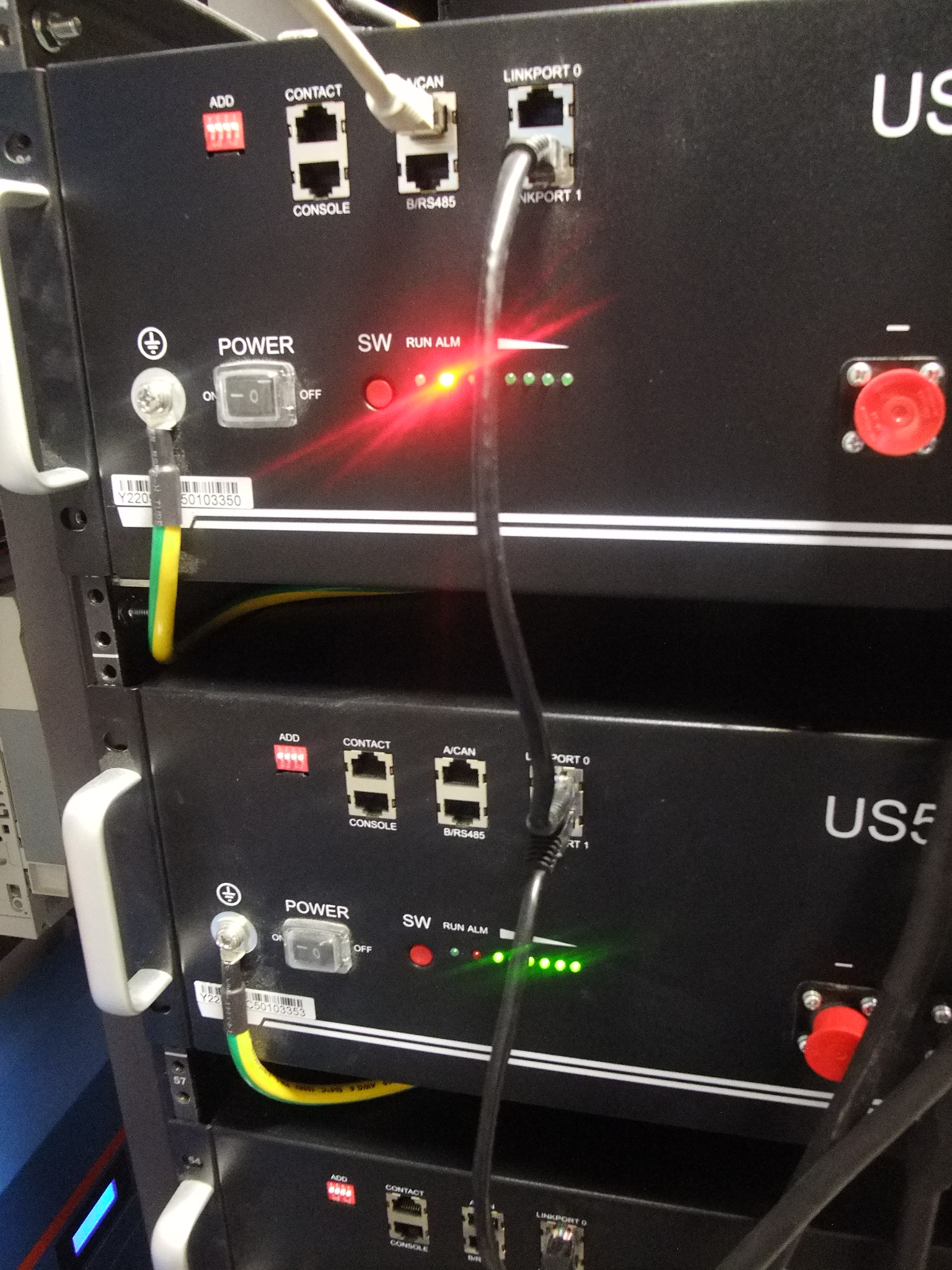
- You need to use straight UTP cable to connect each stack (B/RS485 to ACAN to slave, and so on). You can use the Pylontech cable with the blue tag on it shown "battery connection parallel". BE VERY CAREFUL on the quality of the UTP cable, it can otherwise mess up all CANBUS communication between each stack.
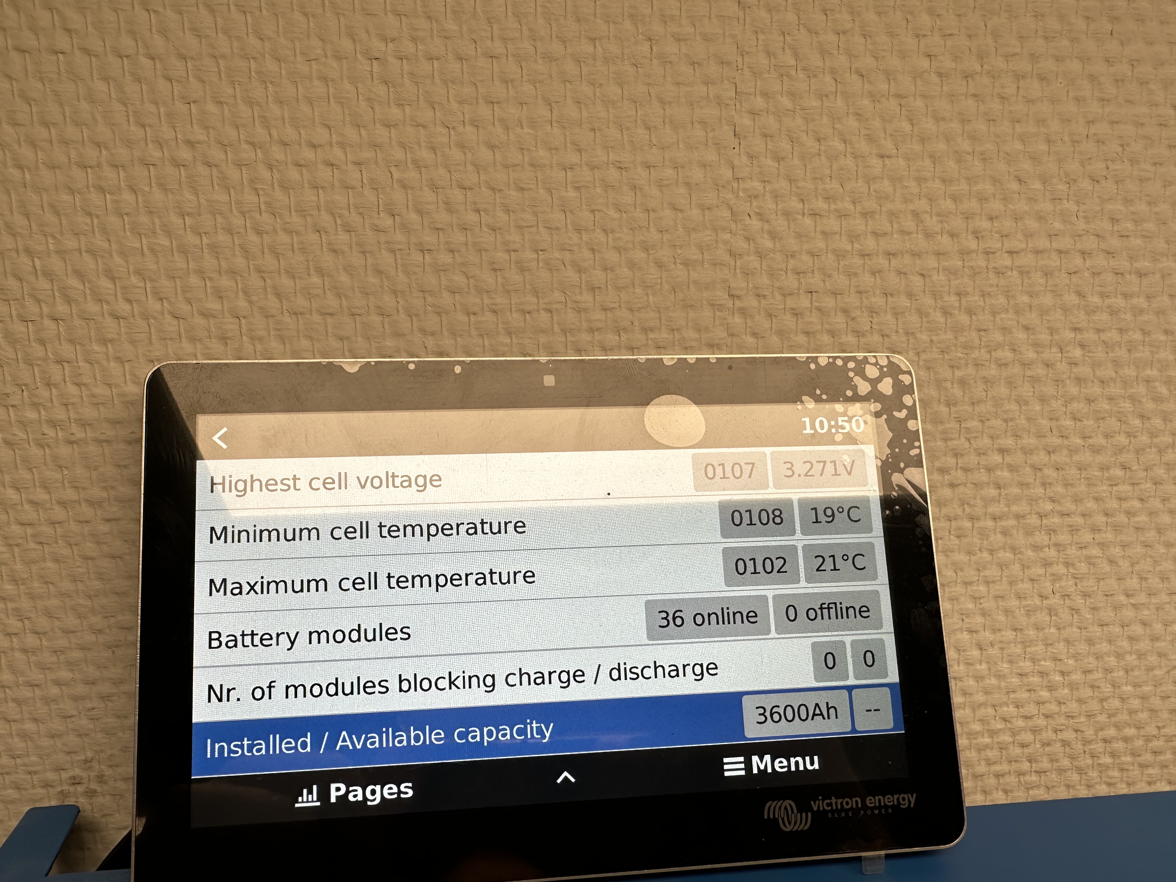
- You have for example 38x US3000C, 3x stacks of 12x US3000C. You let all ADD of the batteries as defaut (all UP). Here's the procedure
- Disconnect LV HUB from master battery.
- Boot up every single battery, sequence 1-2-3 .... to the last battery.
- Then you should hear an alarm buzzer which goes like this " bip, bip, bip" (three times). That means every battery is online and connected.
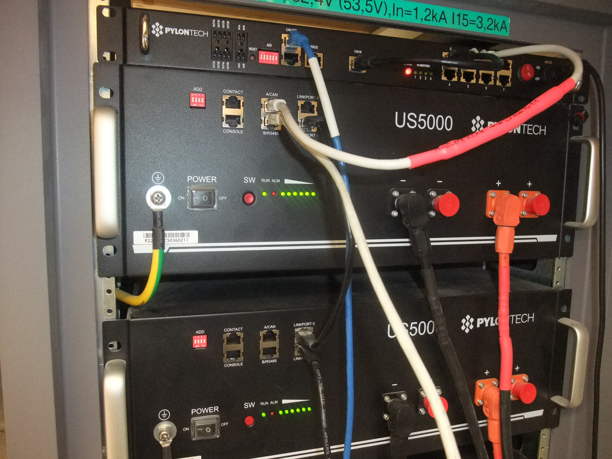
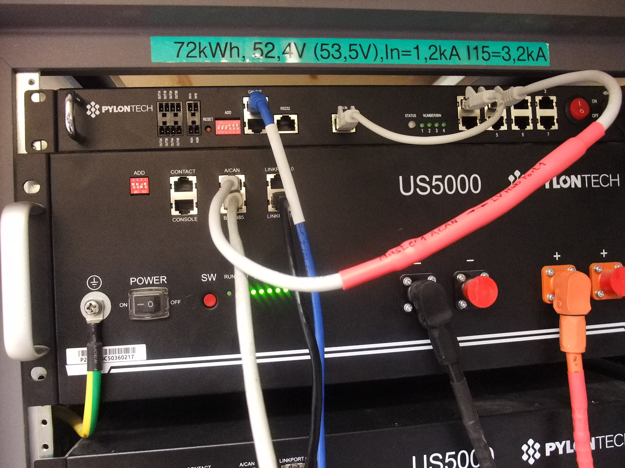
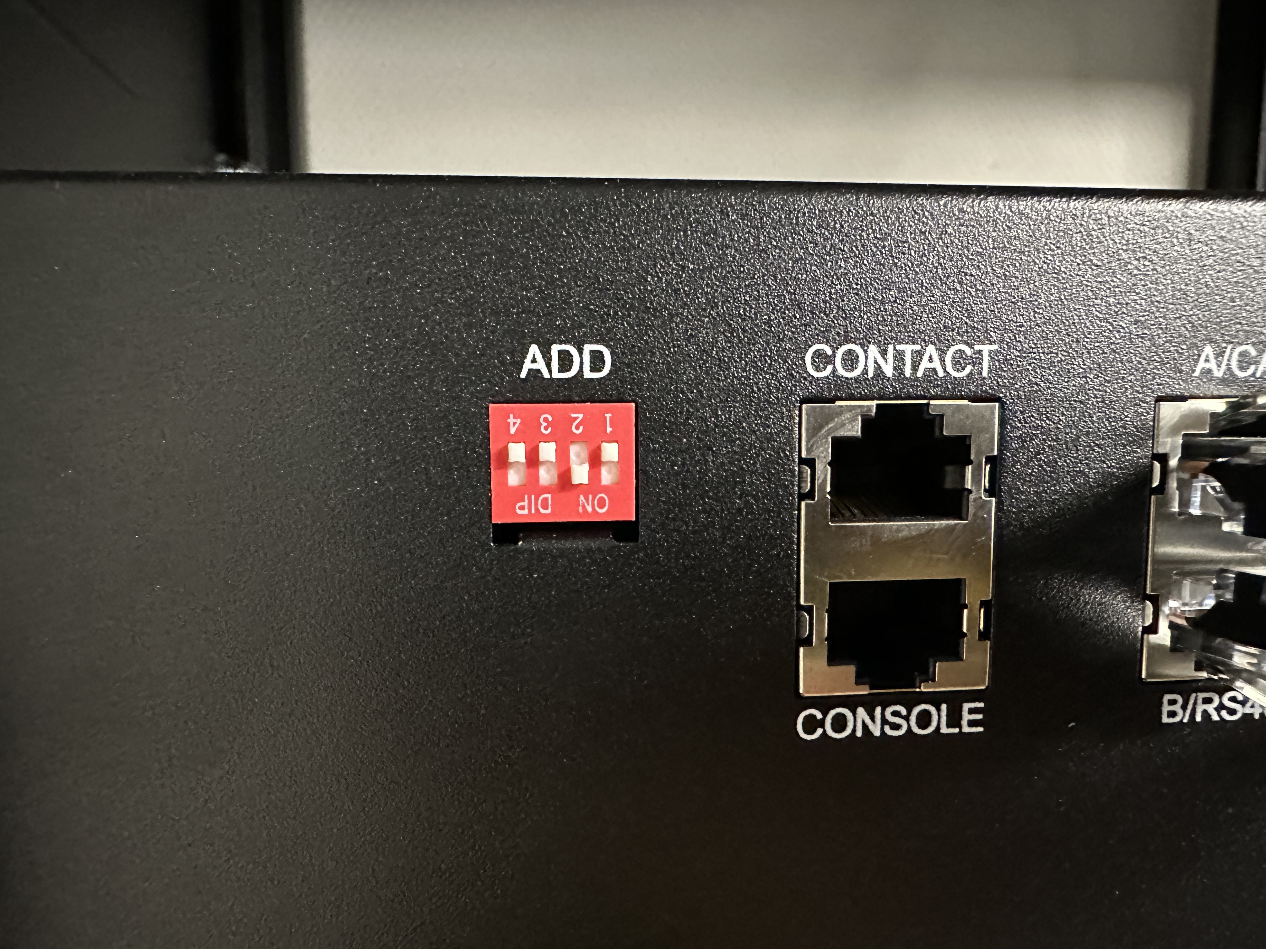
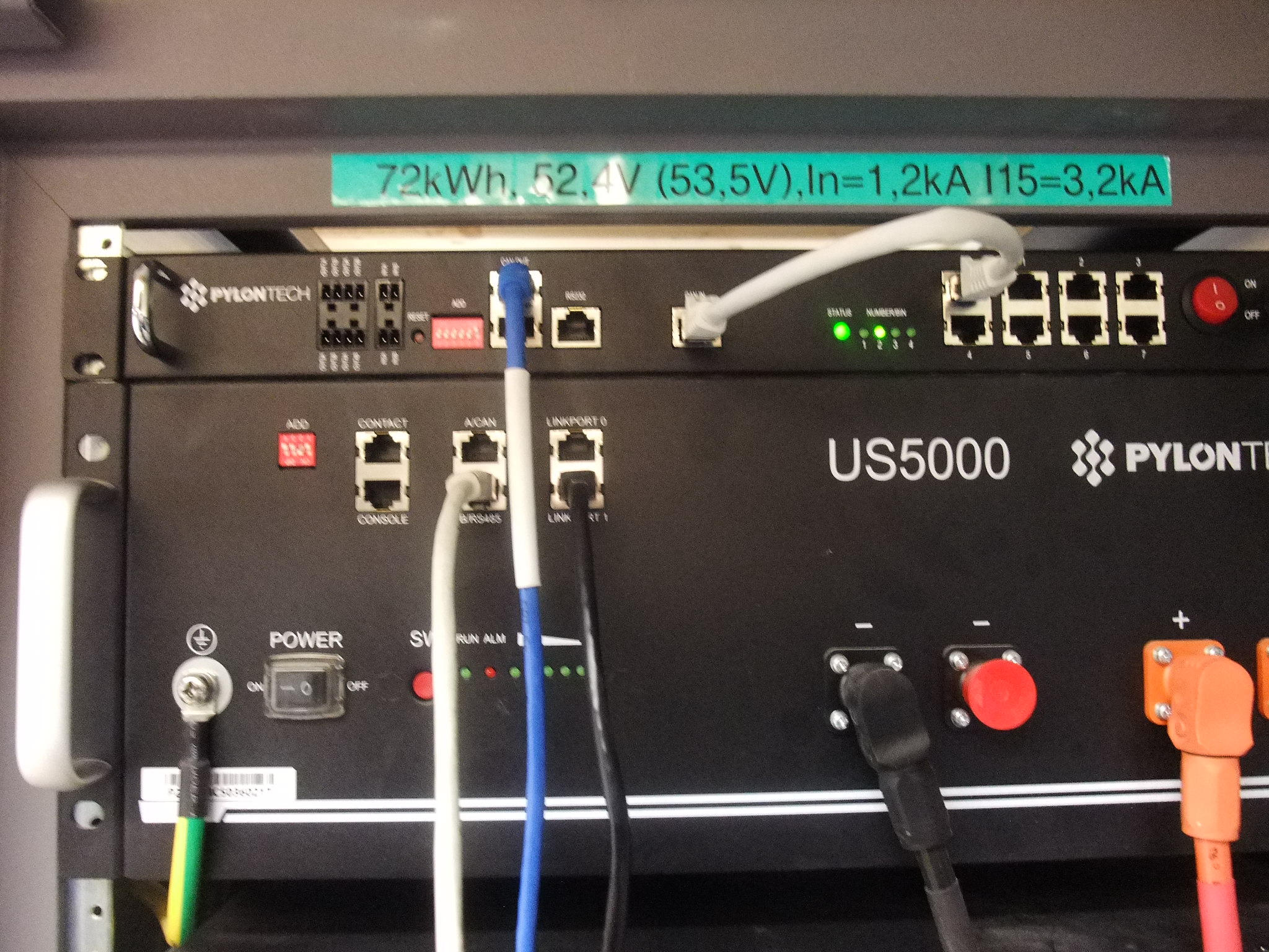
- Then you change the DIP of ONLY the master battery of GROUP 1 to 0010. (please find pictures attached).
- Then you connect the master battery to the LV HUB (using proprietary RJ cable with PIN 1-3 null). Use that specific cable, otherwise communication won't work.
- Then you boot up the LV HUB. You will hear the LV HUB rings. Then all the groups connected shall be shown on the LED.
- Once it is done, you connect the LV HUB to the GX device with TYPE A cable only (Type B will NOT work and will put the LV HUB in error mode). Do not forget to use RJ45 120 Ohm terminator on the BMS CAN unused of the GX device.
- You're all set.
Hope this helps !

