question

perma-batteries avatar image
perma-batteries asked

PYLONTECH LV HUB TROUBLESHOOTING

ello guys,


Given the difficulty of correctly configuring an LV HUB with GX and several clusters of US2000C/3000C, I thought it would be good to lay out our parameters that have been successfull with our Victron systems, after many trials and tribulations. LV HUB manual lacks clarity.


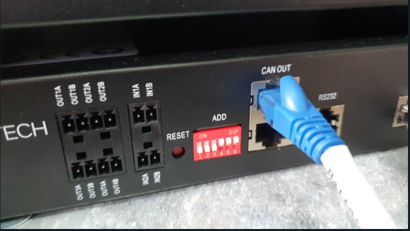
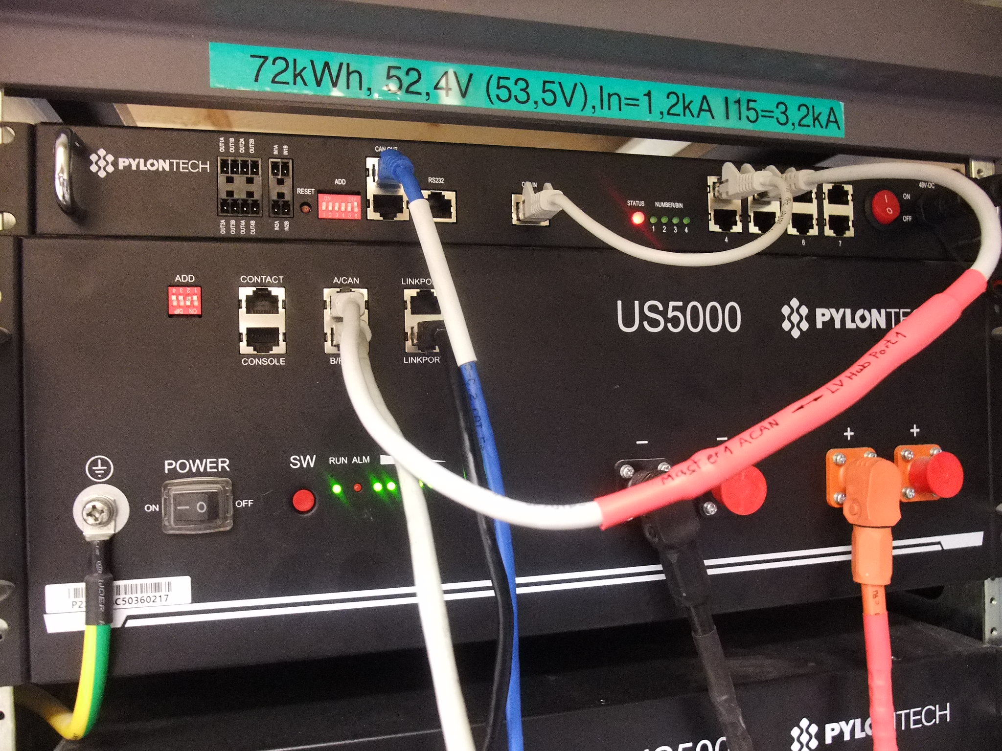
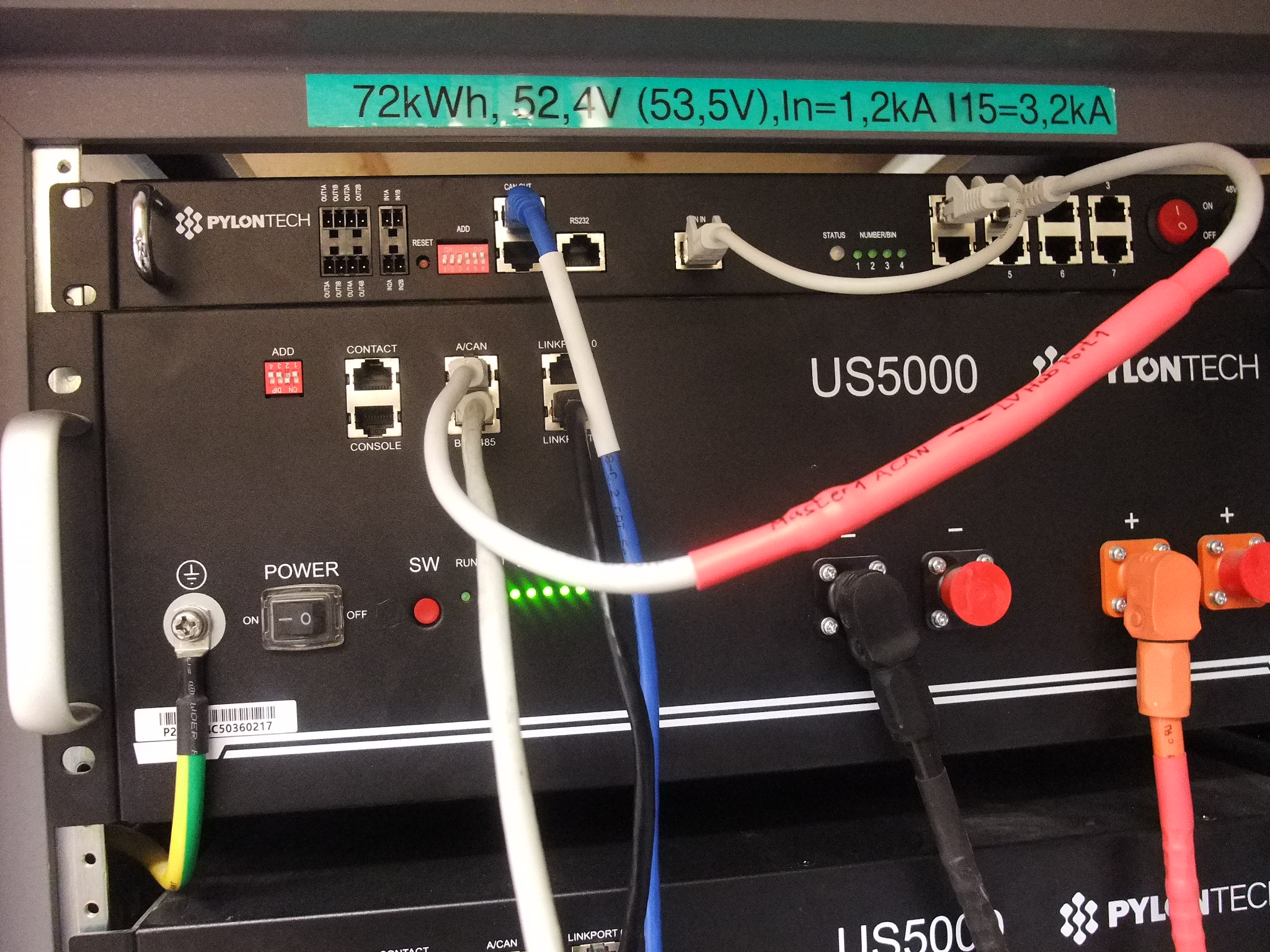
  • VERY IMPORTANT : Adress of the LV HUB must be : 000111 (not shown in any Pylontech manual !)
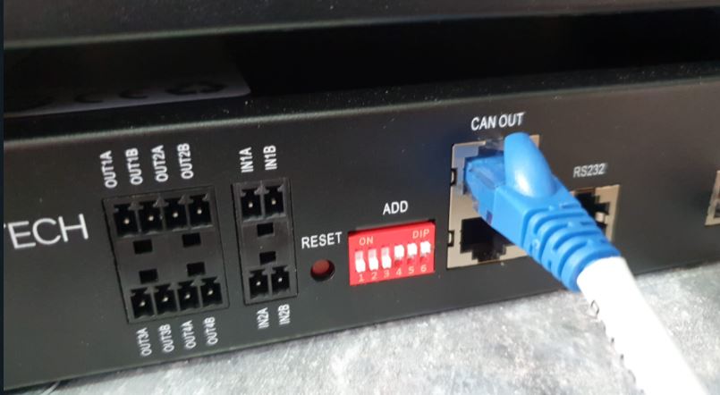
  • 2022-04-08-12-58-59.jpg
  • Cable used : Victron Type A (from "CAN OUT LV HUB to GX).
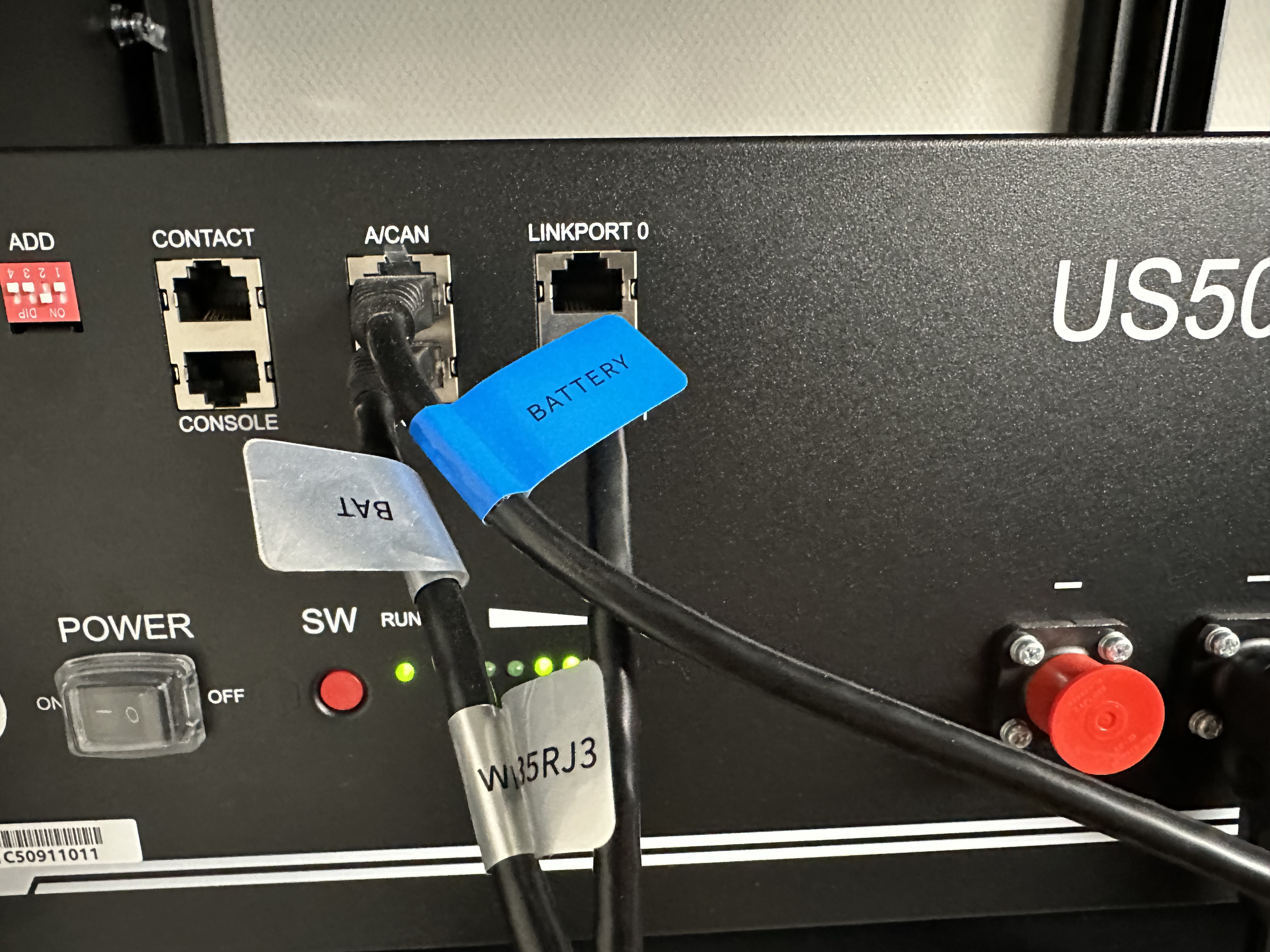
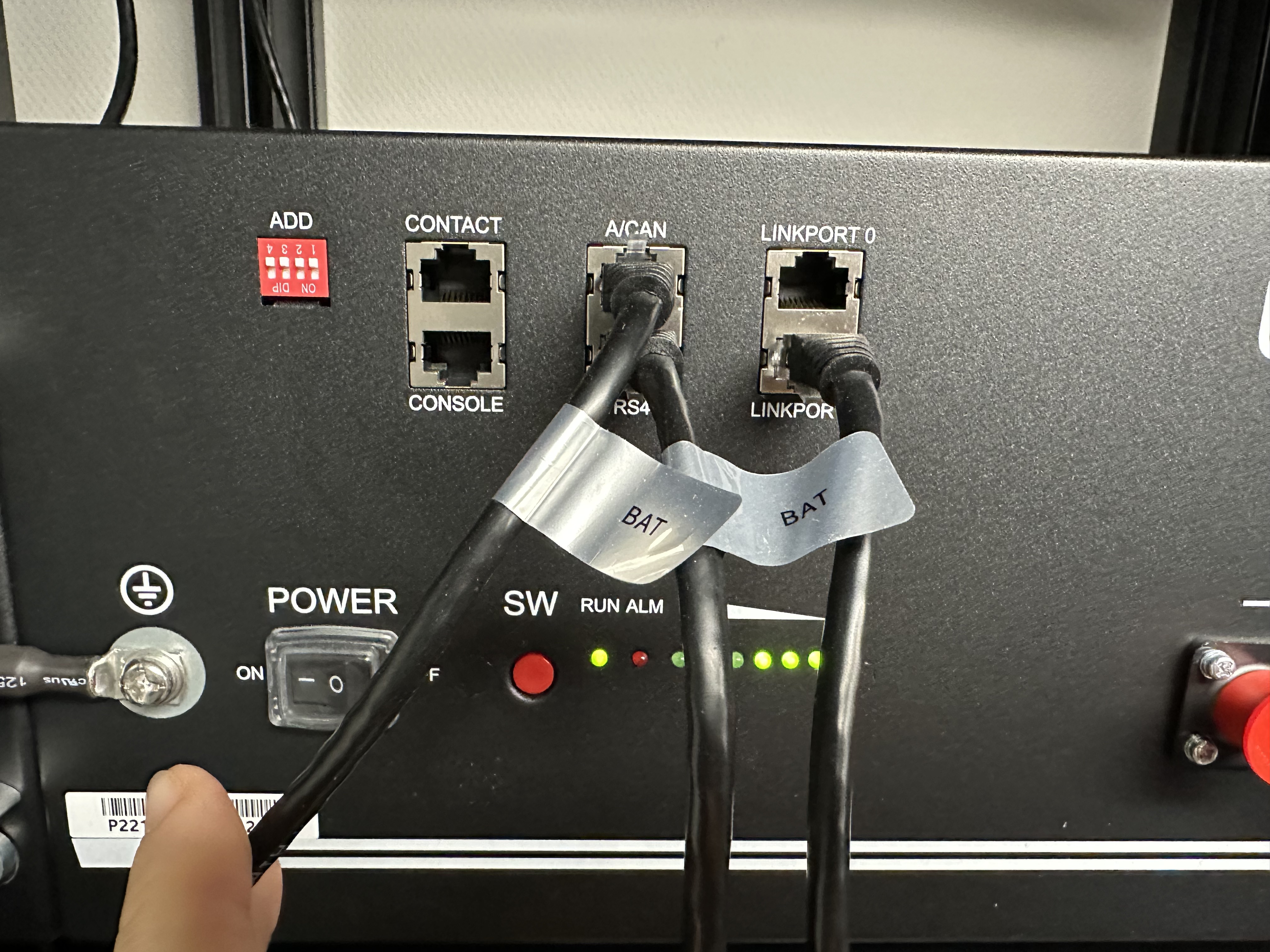
  • Cable used to connect Master US3000C battery (group 1) to the LV HUB port "1" : specific cable supplied by Pylontech (PIN 1/3 : null), with blue tag on it.
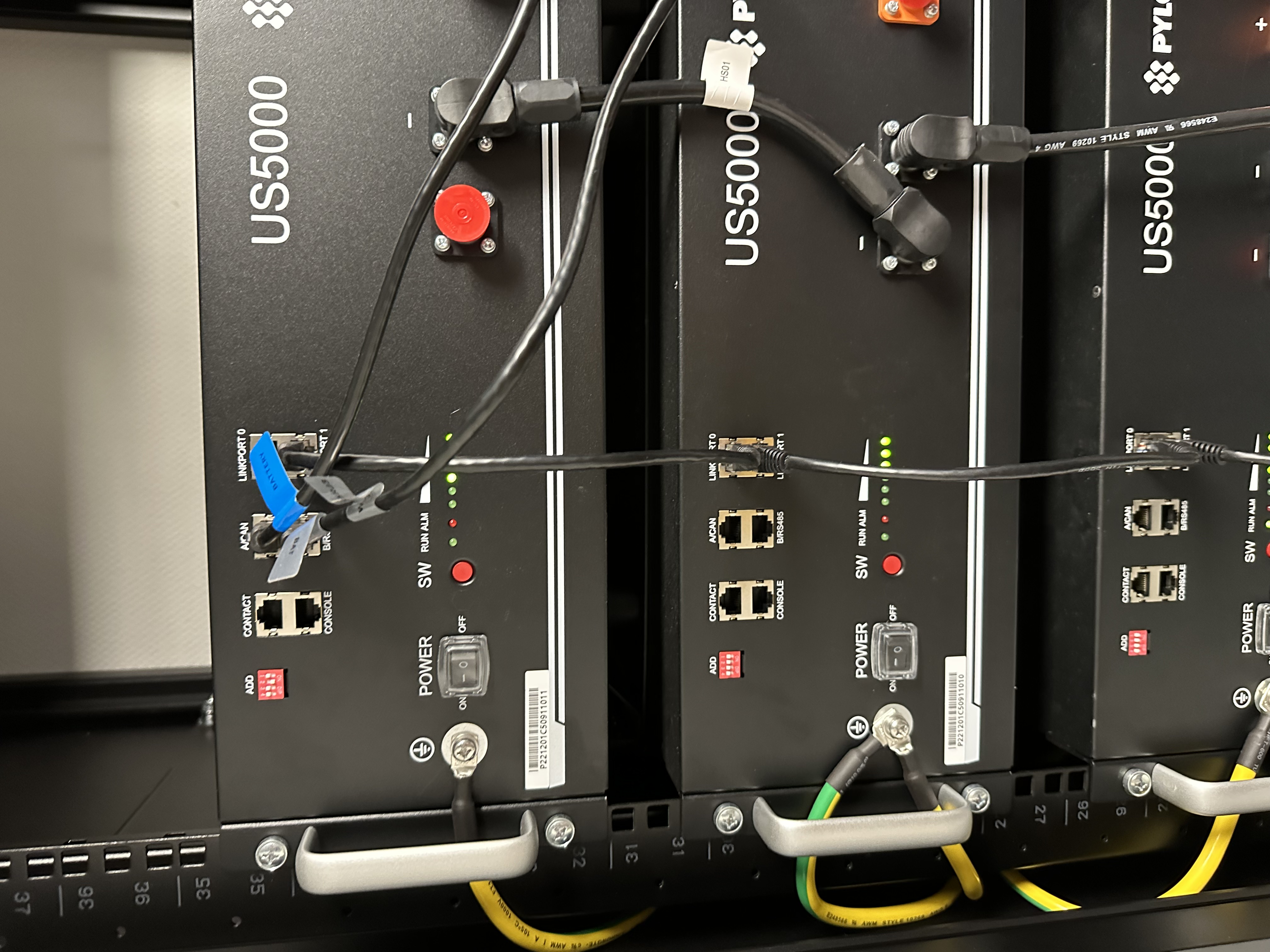
  • You need to use straight UTP cable to connect each stack (B/RS485 to ACAN to slave, and so on). You can use the Pylontech cable with the blue tag on it shown "battery connection parallel". BE VERY CAREFUL on the quality of the UTP cable, it can otherwise mess up all CANBUS communication between each stack.
  • You have for example 38x US3000C, 3x stacks of 12x US3000C. You let all ADD of the batteries as defaut (all UP). Here's the procedure
  • Disconnect LV HUB from master battery.
  • Boot up every single battery, sequence 1-2-3 .... to the last battery.
  • Then you should hear an alarm buzzer which goes like this " bip, bip, bip" (three times). That means every battery is online and connected.
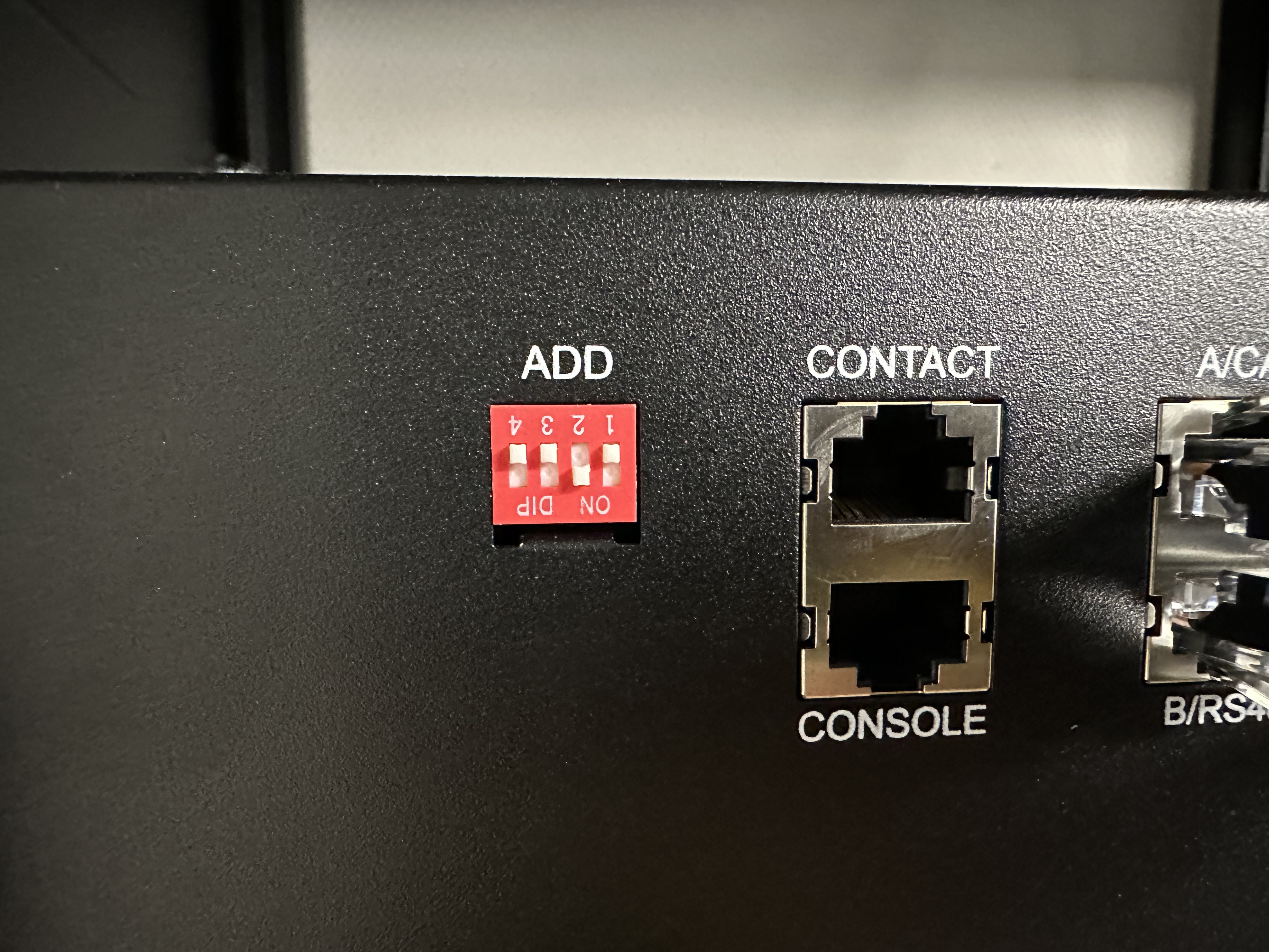
  • Then you change the DIP of ONLY the master battery of GROUP 1 to 0010. (please find pictures attached).
  • Then you connect the master battery to the LV HUB (using proprietary RJ cable with PIN 1-3 null). Use that specific cable, otherwise communication won't work.
  • Then you boot up the LV HUB. You will hear the LV HUB rings. Then all the groups connected shall be shown on the LED.
  • Once it is done, you connect the LV HUB to the GX device with TYPE A cable only (Type B will NOT work and will put the LV HUB in error mode). Do not forget to use RJ45 120 Ohm terminator on the BMS CAN unused of the GX device.
  • You're all set.


Hope this helps !
Pylontechpylontech lv hub
3 comments
2 |3000

Up to 8 attachments (including images) can be used with a maximum of 190.8 MiB each and 286.6 MiB total.

Michael Timler avatar image Michael Timler commented ·
Unfortunately, the announced picture 2022-04-08-13-00-36.jpg is missing in the attachment. But exactly this information would be very valuable. Is there a possibility, that you will post this as well?


Thank you for all this valuabale informations!

Yours Michael, struggling with exactly these problems right at the moment.
0 Likes 0 ·
perma-batteries avatar image perma-batteries Michael Timler commented ·

Hello Michael,

2022-04-13-22-53-36.png

No prob ! Please find picture again.

For help, contact us at contact@perma-batteries.com


0 Likes 0 ·
dustin76 avatar image dustin76 commented ·
Hi,


Thank you for the help. I cant seem to get my hands on the cable that goes from 3000C master to LV hub that you speak of. How exactly is it pinned out, so i could crimp my own... Not too sure what you mean 1/3:null


0 Likes 0 ·
34 Answers
wkirby avatar image
wkirby answered ·

Thank you. I think this will be very helpful.

2 |3000

Up to 8 attachments (including images) can be used with a maximum of 190.8 MiB each and 286.6 MiB total.

Rob Fijn avatar image
Rob Fijn answered ·

Thank you very much for your post. Very valuable.

2 |3000

Up to 8 attachments (including images) can be used with a maximum of 190.8 MiB each and 286.6 MiB total.

markus avatar image
markus answered ·

Many thanks. Should be included in the Victron-Pylontech documents.

2 |3000

Up to 8 attachments (including images) can be used with a maximum of 190.8 MiB each and 286.6 MiB total.

mvader (Victron Energy) avatar image
mvader (Victron Energy) answered ·

Hi @perma-batteries , thank you!

I asked Pylon to review above, their comment was that its all correct except for the first point:

The address shall be 000001 to communication with Victron and common CANBUS inverter, 000101 is for communication with a dedicated brand of inverter.


Could you amend that in your post?


Also I briefly read and compared page 8 of their LV Hub manual ("Communication HUB LV-HUB Production Manual, Information version 2.2"), and the process described in their is almost the exact same as what you posted above. Or not?

In general I want to try and avoid duplicate information: best for all this is if its properly documented in the Pylontech documentation. And not copied accross onto our documentation.


All the best, Matthijs

2 |3000

Up to 8 attachments (including images) can be used with a maximum of 190.8 MiB each and 286.6 MiB total.

perma-batteries avatar image
perma-batteries answered ·

Hi Matthijs,


Thanks a lot for your response. Pylontech's reponse however is misleading as we've been exchanging in them on several times. Reality is that they're basically clueless about how to proper set up the LV HUB with Victron and after countless combinations of the DIP switch tests and many trials and errors we came to the conclusion that only the above configuration would enable proper communication between CAN of the LV HUB and GX. This is : 000111 on the LVHUB, NOT what their documentation says. They keep telling us "refer to the documentation", this is expected from a Chinese brand, but we found out that their support is not up to the hype and definitely not up to such a major battery manufacturer. We exchanged with fellow Victron installers (Mexico, Spain, etc..) which are also using our LV HUB parameters with success. If we set up the parameter 000001, we have NO CANBUS communication with GX at all. I think therefore Pylontech should try to test their product (LV HUB) with Victron, and see for themselves the issue we faced.


2 |3000

Up to 8 attachments (including images) can be used with a maximum of 190.8 MiB each and 286.6 MiB total.

offroadflow avatar image
offroadflow answered ·

Thanks for the effort.

But unfortunately the DIP setting of the HUB can't be right since 000111 puts the hub right away in error mode (red blinking Led).

With 000001 it's green blinking (not connected to the GX).

My setup I try to reconnect to a Venus is 3 stacks of 4 US2000 through a Upower hub. It used to work fine but after having to replace the Venus it wont be recognized anymore.

And nobody has a clue why. Whether the spanish "professionals" nor me nor does Victron themselves at least try to solve this weird mystery.

Not happy with the aftersale at all folks!


2 |3000

Up to 8 attachments (including images) can be used with a maximum of 190.8 MiB each and 286.6 MiB total.

Rob Duthie avatar image
Rob Duthie answered ·

Hi All


Yes being though that process to fix the issues i had to load new firmware into the LV hub and also the batteries got new firmware as well. to solve the issue.

this was for the UP3000 series.

I have the latest manaul from them Ver 2.2 for configurations

I have the new firmware and files, software to do it on hand.

Regards

Rob D

NZ

5 comments
2 |3000

Up to 8 attachments (including images) can be used with a maximum of 190.8 MiB each and 286.6 MiB total.

offroadflow avatar image offroadflow commented ·
Hello @Rob Duthie. Thanks for answering!

I assume the firmware for the 3000 is not for the 2000...

And my hub seems to be the same, even tho it carries another brands name.

Shall I have a look at the Pylons website for a new 2000 firmware first or do you have this as well?

Thanks again!

Much appreciated

0 Likes 0 ·
Rob Duthie avatar image Rob Duthie offroadflow commented ·
Hi

For both the 2000 and 3000. You won't find it on the web site, you have to know someone which i did after having issues, and they sent me the interface leads and all the new firmware and software to use.

The interface leads are easy to make your self if required.

Regards

Rob D

NZ

1 Like 1 ·
Show more comments
Mike Dorsett avatar image
Mike Dorsett answered ·

I'm looking at the possibility of a larger system for a client. After looking through a couple of related posts too, it seems that the maximum number of US3000C connected to an LV-hub is 40. Is it possible to connect multiple hubs - either to each other or to the Venus device? The system under consideration would need possibly 3 or 4 hubs to be connected...

2 comments
2 |3000

Up to 8 attachments (including images) can be used with a maximum of 190.8 MiB each and 286.6 MiB total.

offroadflow avatar image offroadflow commented ·
Yes, I've seen multiple hubs connected to one main hub.

Just cant remember where... I reckon it was the official PylonTech website tho

0 Likes 0 ·
apfelsaft avatar image
apfelsaft answered ·

Thank you for your guide.


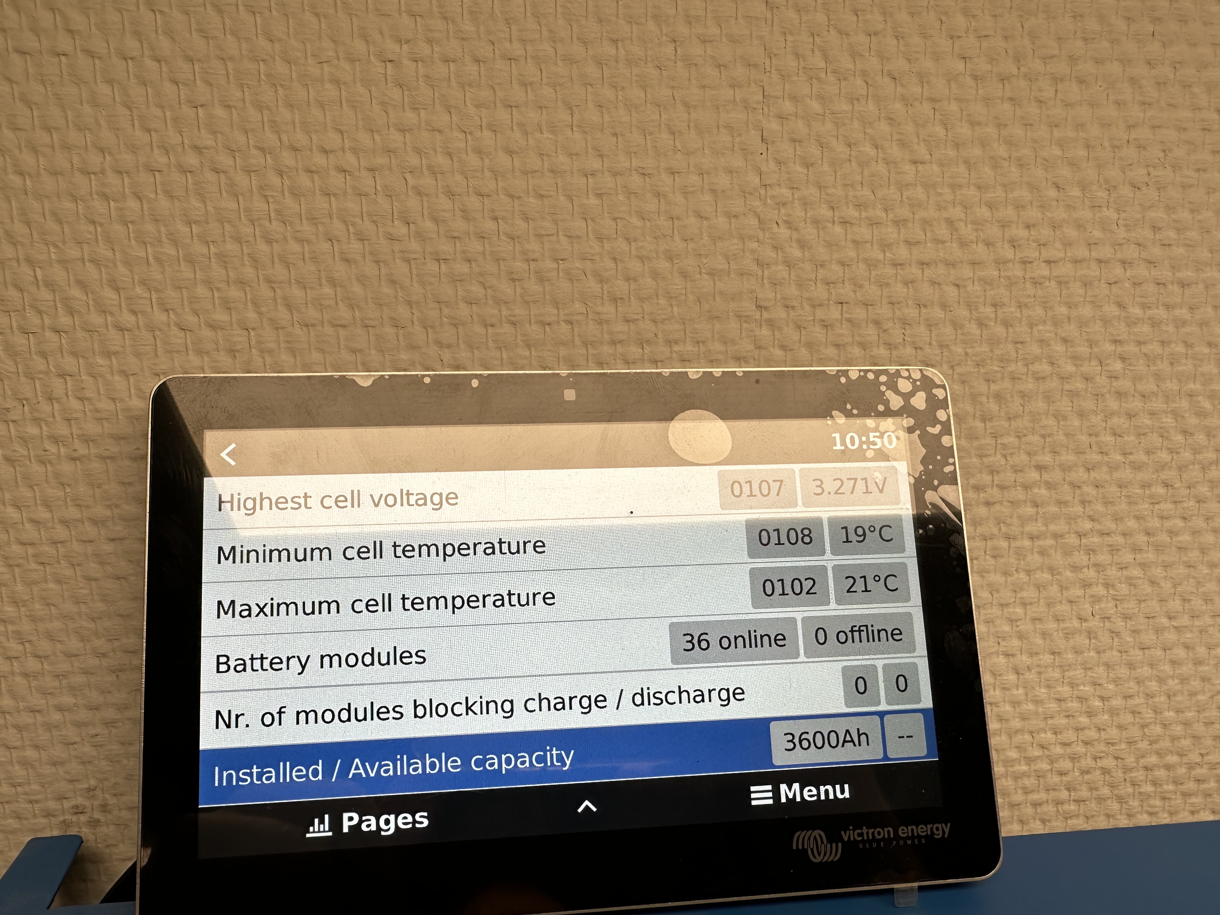
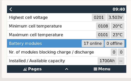
I have 4x5 US3000C but the LV-Hub only shows 3 Groups. Sometimes 4 and than after a while 3. Also the installed and available capacity shown on the cerbo is not correct.


Will a firmware update of the LV-Hub help?

2 |3000

Up to 8 attachments (including images) can be used with a maximum of 190.8 MiB each and 286.6 MiB total.

apfelsaft avatar image
apfelsaft answered ·

After using the latest Firmware for the LV-Hub my 20x US3000C are displayed correctly. The Version is 1.8 and you can get it by mailing jeff.cheaung@pylontech.com.cn


To connect the groups to the LV-Hub we used the LV-Hub manual. It's working as described but you have to take exactly those steps in chapter 3.3 and use the matching cables. Thats essential.


Also very important if searching for manuals that you look for the exact battery you have. There are mayor differences between US3000C, US3000 and so on.

1 comment
2 |3000

Up to 8 attachments (including images) can be used with a maximum of 190.8 MiB each and 286.6 MiB total.

flaux avatar image flaux commented ·
Hey Apfelsaft


Do you really think that Jeff send a firmware with instructions, do update the LV Hub ?

0 Likes 0 ·
Mark Whittaker avatar image
Mark Whittaker answered ·

Hi all,

Here is a drawing I make up after my LV Hub experience.

HUB.pdf


hub.pdf (1.8 MiB)
2 |3000

Up to 8 attachments (including images) can be used with a maximum of 190.8 MiB each and 286.6 MiB total.

Wietse Wind avatar image
Wietse Wind answered ·

Hi all,

Sorry to re-open a topic from a while ago, but I have an LV Hub with the same problems. It's running old (1.5) firmware. I tried to mail Pylontech, but it has been weeks and despite the reminders I am not getting a reply.

Does someone perhaps have the firmware & update instructions as obtained from Pylontech before?

Yours,
Wietse

-- @Rob Duthie @apfelsaft

2 |3000

Up to 8 attachments (including images) can be used with a maximum of 190.8 MiB each and 286.6 MiB total.

Rob Duthie avatar image
Rob Duthie answered ·

Hi

I do. Need version firmware 1.7 for LV Hub.

Regards

Rob D

NZ

2 |3000

Up to 8 attachments (including images) can be used with a maximum of 190.8 MiB each and 286.6 MiB total.

apfelsaft avatar image
apfelsaft answered ·

Hi

I totally understand if you have the same problems as I had and no one is answering.

So here attached you'll find Firmware 1.8 for the. LV Hub

Please be aware that you can destroy the system if you do something wrong updating the firmware.

AGAIN: THE CABELING IS ESSENTIAL! READ MY ANSWER UP IN THE ARTICLE


LVHUB_V1.8.bin.zip


lvhub-v18bin.zip (99.7 KiB)
1 comment
2 |3000

Up to 8 attachments (including images) can be used with a maximum of 190.8 MiB each and 286.6 MiB total.

Wietse Wind avatar image Wietse Wind commented ·

Thank you *very* much! I really appreciate it!

0 Likes 0 ·
Wietse Wind avatar image
Wietse Wind answered ·

@apfelsaft Thanks again. The firmware update worked.

I then ended up having a weird problem where cell voltages, installed # of batteries, etc. weren't displayed correctly. By combining the info provided by you & @apfelsaft @Mark Whittaker

Besides the firmware update, the final trick ended up being what @Mark Whittaker described: boot the batteries in 0000 while disconnected from LV Hub, then (after 3x master beep) change to 0010, THEN connect master to LV Hub, then boot LV Hub.

Finally :D Thanks for your help and info!

1689116975871.png


1689116975871.png (85.6 KiB)
2 comments
2 |3000

Up to 8 attachments (including images) can be used with a maximum of 190.8 MiB each and 286.6 MiB total.

Rob Duthie avatar image Rob Duthie commented ·
Hi

Also you might need to update the battery firmware as well to report correctly.

Also what version of Venus are you running?

All helps as it reports a alot with these updates etc being done.

Regards

Rob D

NZ

0 Likes 0 ·
Wietse Wind avatar image Wietse Wind Rob Duthie commented ·

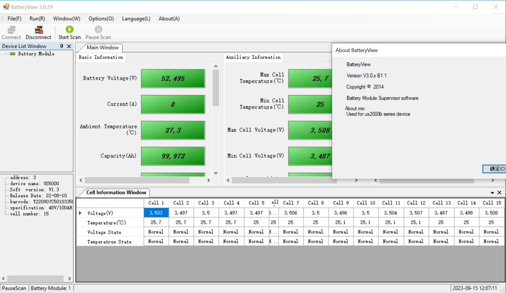
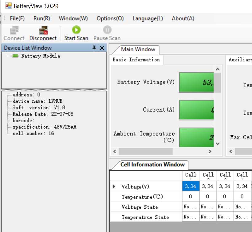
I had to update the battery firmware as well, indeed. Here's the most recent (two weeks ago) BatteryView application and US5000 firmware I have received from Pylontech, and the LV Hub firmware as received yesterday two posts up:

LV HUB: https://knn1kbh.dlvr.cloud/lvhub-v18bin-c.zip

US5000: https://ema7whp.dlvr.cloud/US5000_st1.4+e21.6.zip (DO NOT EXTRACT, UPLOAD AS ZIP)

BatteryView to update the firmware:

https://knn1kbh.dlvr.cloud/BatteryView_3.0.29%20B1.1.zip

I used a cable connection like this to connect to the batteries:
https://www.youtube.com/watch?v=qj07v10E4XA

So now the batteries are running (as provided above)

The LV Hub is running 1.8 (as provided above)

The GX is running 3.00

0 Likes 0 ·
janvi avatar image
janvi answered ·

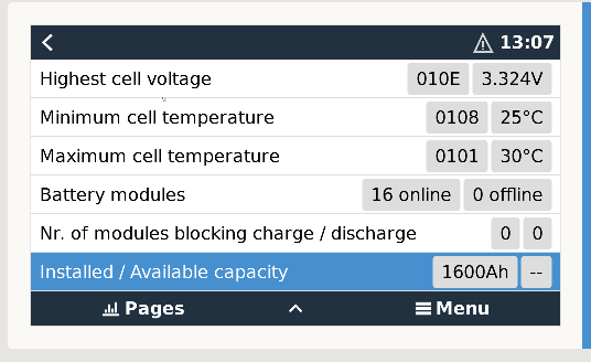
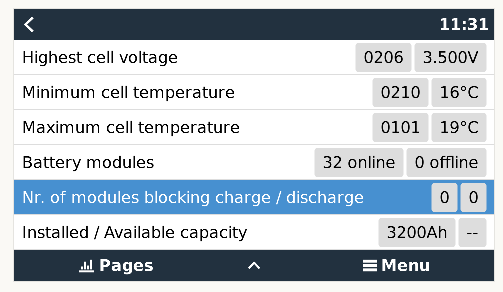
Also struggle with very similar problems here when I try to connect 2 stacks of 16 pcs US5000 by LV Hub. Hub LEDs are green and indicate 2 accepted stacks.

Only one stack with 16 devices US5000 appear in the device manager while I expect 32 devices from CAN bus with reported capacity of 3200 Ah.

Probably this is also the reason for incorrect dashboard calculations. It shows only about half charging current what exists physically and PV Power to total power is strongly out of balance. If I use only one stack of 16 Pylontechs without LV hub, the number of devices and dashboard calculations seems ok.


Will this FW updates help and are there any instructions on how to do the updates (serial?)?

dscf6756.jpg

screenshot-from-2023-09-07-13-08-06.png

screenshot-from-2023-09-07-12-15-16.png


2 |3000

Up to 8 attachments (including images) can be used with a maximum of 190.8 MiB each and 286.6 MiB total.

janvi avatar image
janvi answered ·

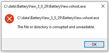
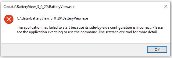
The files in cloud linked by @Wietse Wind are definetly corrpupted. They only produces error messages like attached. There are other copies of BatteryView 3.0.29 what work without problems.

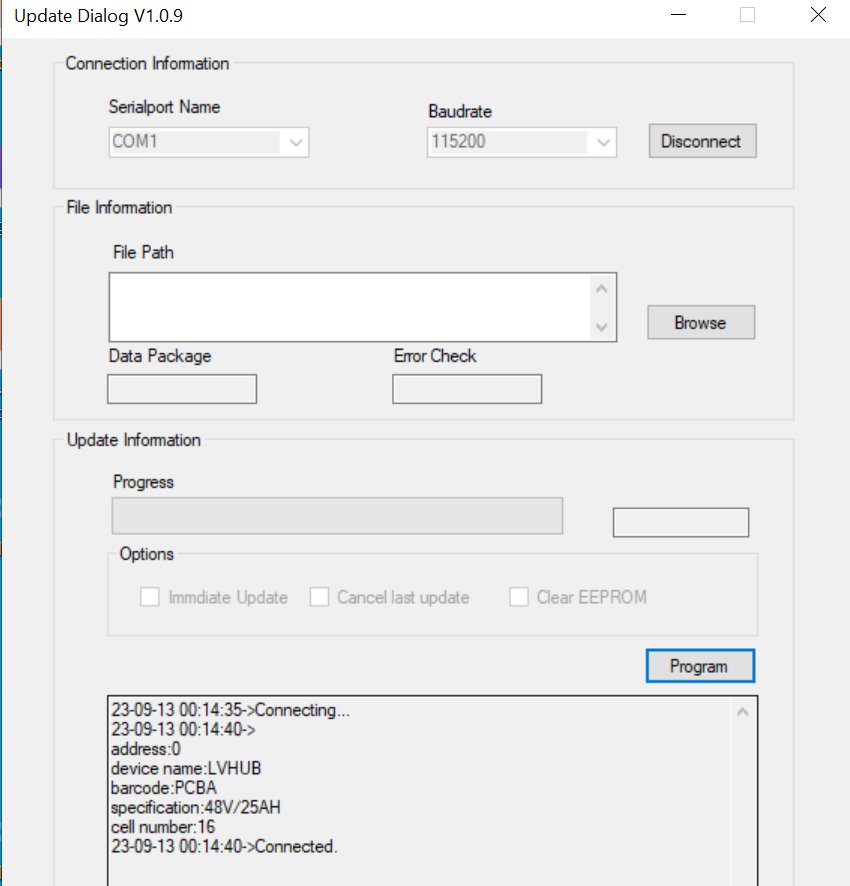
Anyhow I found another update tool at the webpage of Effekta, a German Pylontech dealer.

Anybody here who has more than 16 US5000 in operation ? My LV hub FW is V1.8 and my US5000 run FW 1.3 from 10th of Aug. 2022.


batviewvshostexe.jpgbatterzviewexe.jpgupdatedialog.png


batterzviewexe.jpg (26.1 KiB)
updatedialog.png (97.4 KiB)
2 |3000

Up to 8 attachments (including images) can be used with a maximum of 190.8 MiB each and 286.6 MiB total.

Wietse Wind avatar image
Wietse Wind answered ·

@Janvi
> Anbybody here who has more than 16 US5000 in operation ? My LV hub FW is V1.8 and my US5000 run FW 1.3 from 10th of Aug. 2022.

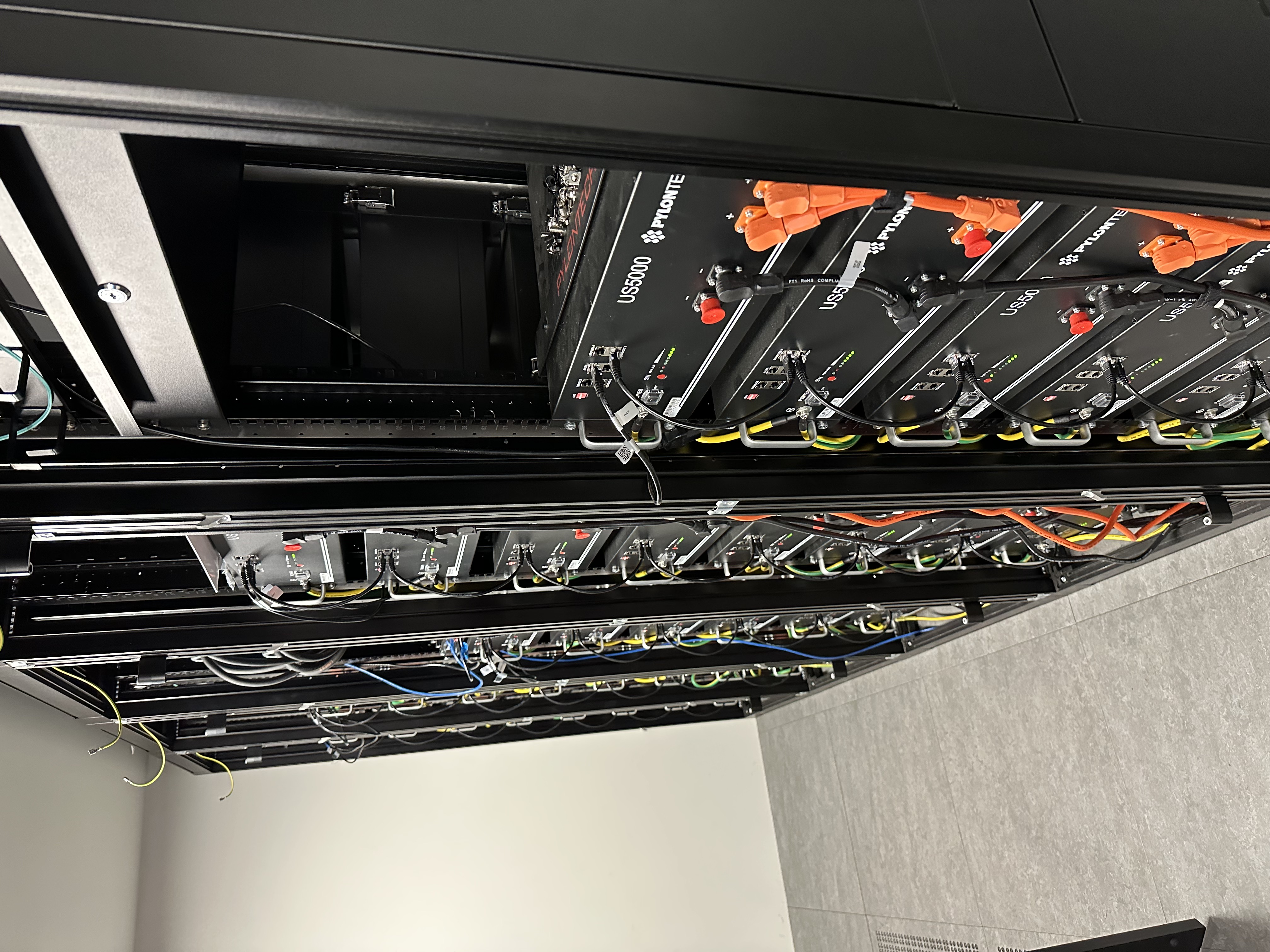
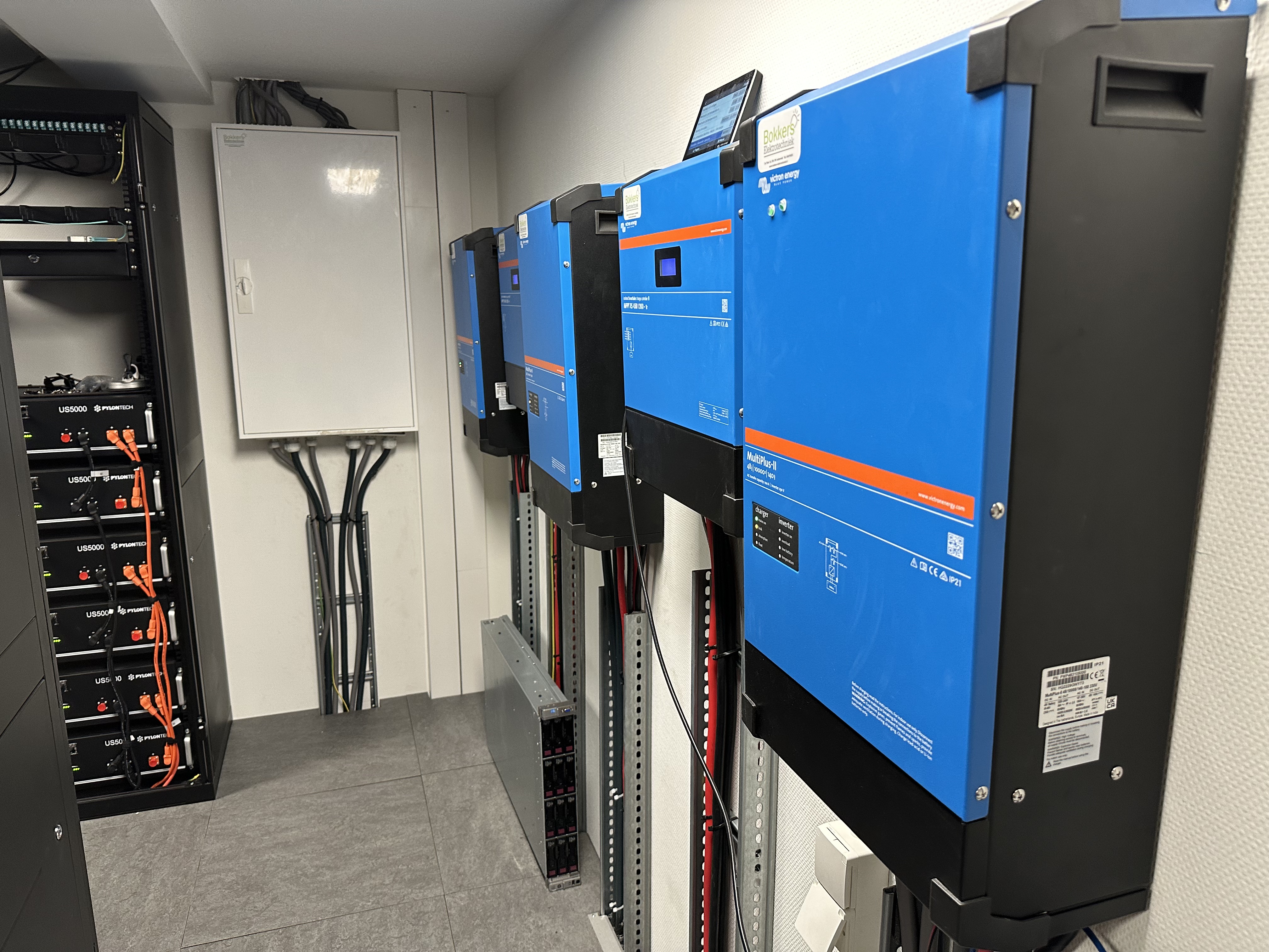
I have 36x US5000 in operation with LV-Hub.

I can send over some pics of how I configured the DIP switches on batteries, LV Hub, cabling, etc.?

1 comment
2 |3000

Up to 8 attachments (including images) can be used with a maximum of 190.8 MiB each and 286.6 MiB total.

Rob Duthie avatar image Rob Duthie commented ·
Hiu

Have you emailed to Plyontech them selves in China? They do have good back up with issues. Lucas is a good contact there.

I have installed a max of 12x US2000 with the LV hub unit and others using US3000 with LV hub etc thgey need firmware updates for sure.

Regards

Rob D

NZ

0 Likes 0 ·
janvi avatar image
janvi answered ·

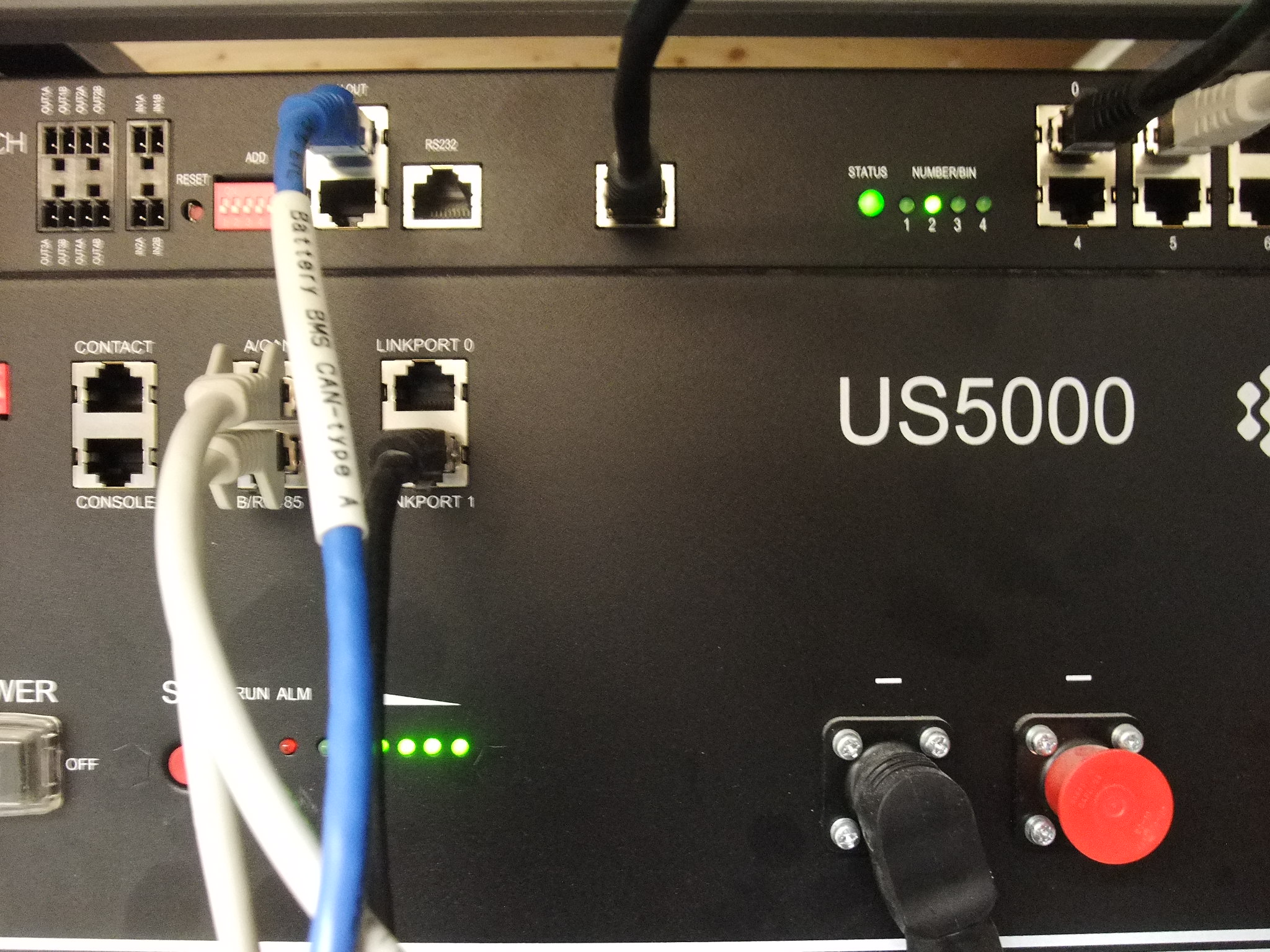
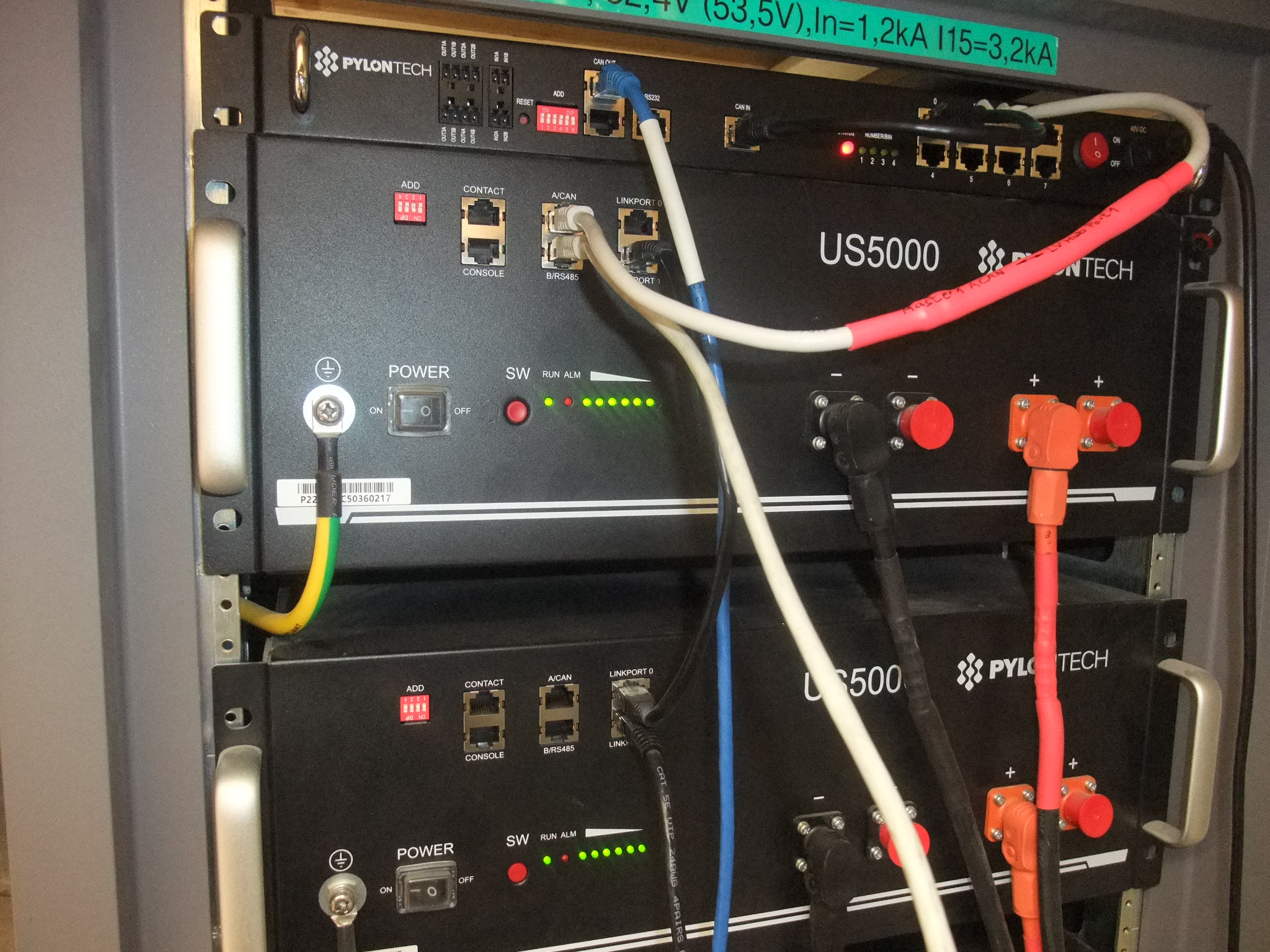
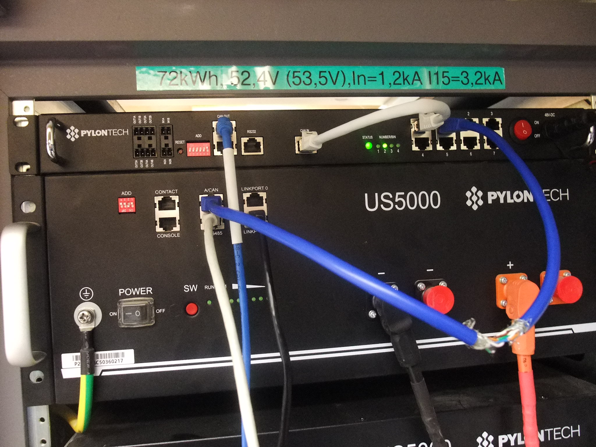
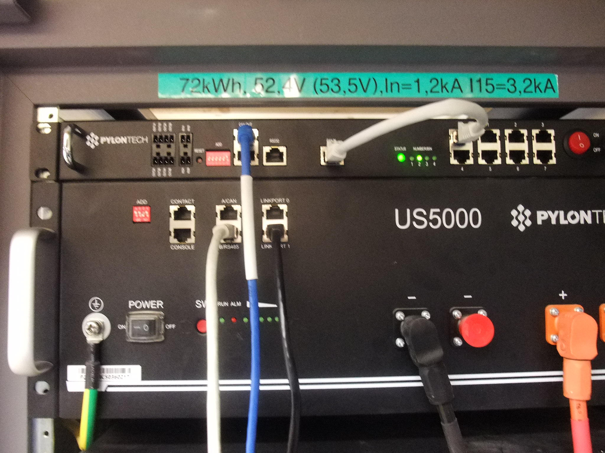
@Wietse Wind pls post your photo here as this allows everybody to see the working setup. Attached is my stack 1 with master1 and hub as it should work. Only red LED is flashing.

Hub switch 6 is down.

Battery switch 2 should be down but same problem anyway

Cable with red shrink tube from A/CAN to hub port 1 pin 1,2,3 disconnected

Blue cable wiith white shrink tube is Victron type A and connects to Cerbo

B/RS485 cable is 1:1 and connects to A/CAN of stack 2dscf6784.jpg


dscf6784.jpg (711.2 KiB)
2 |3000

Up to 8 attachments (including images) can be used with a maximum of 190.8 MiB each and 286.6 MiB total.

janvi avatar image
janvi answered ·

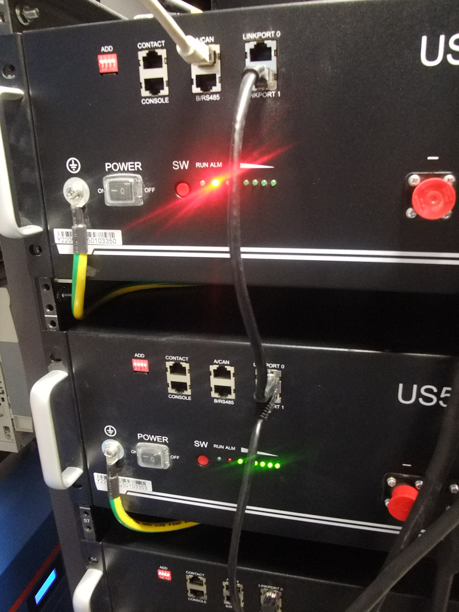
more fotos with diffrent switch settings. Power up sequence is

- wait for 3x beep

- push switch 2 of master 1 down

- connect hub and switch on

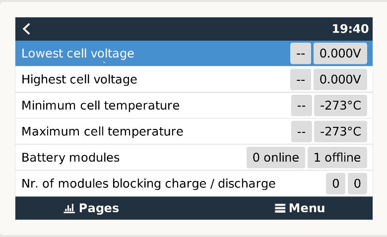
There is any communication with my Cerbo but always reports 0 online 1 offline with all values null.

dscf6789.jpgdscf6790.jpglvhub1.png


dscf6789.jpg (716.9 KiB)
dscf6790.jpg (717.9 KiB)
lvhub1.png (36.4 KiB)
2 |3000

Up to 8 attachments (including images) can be used with a maximum of 190.8 MiB each and 286.6 MiB total.

Wietse Wind avatar image
Wietse Wind answered ·

@Janvi Here's what works for me:

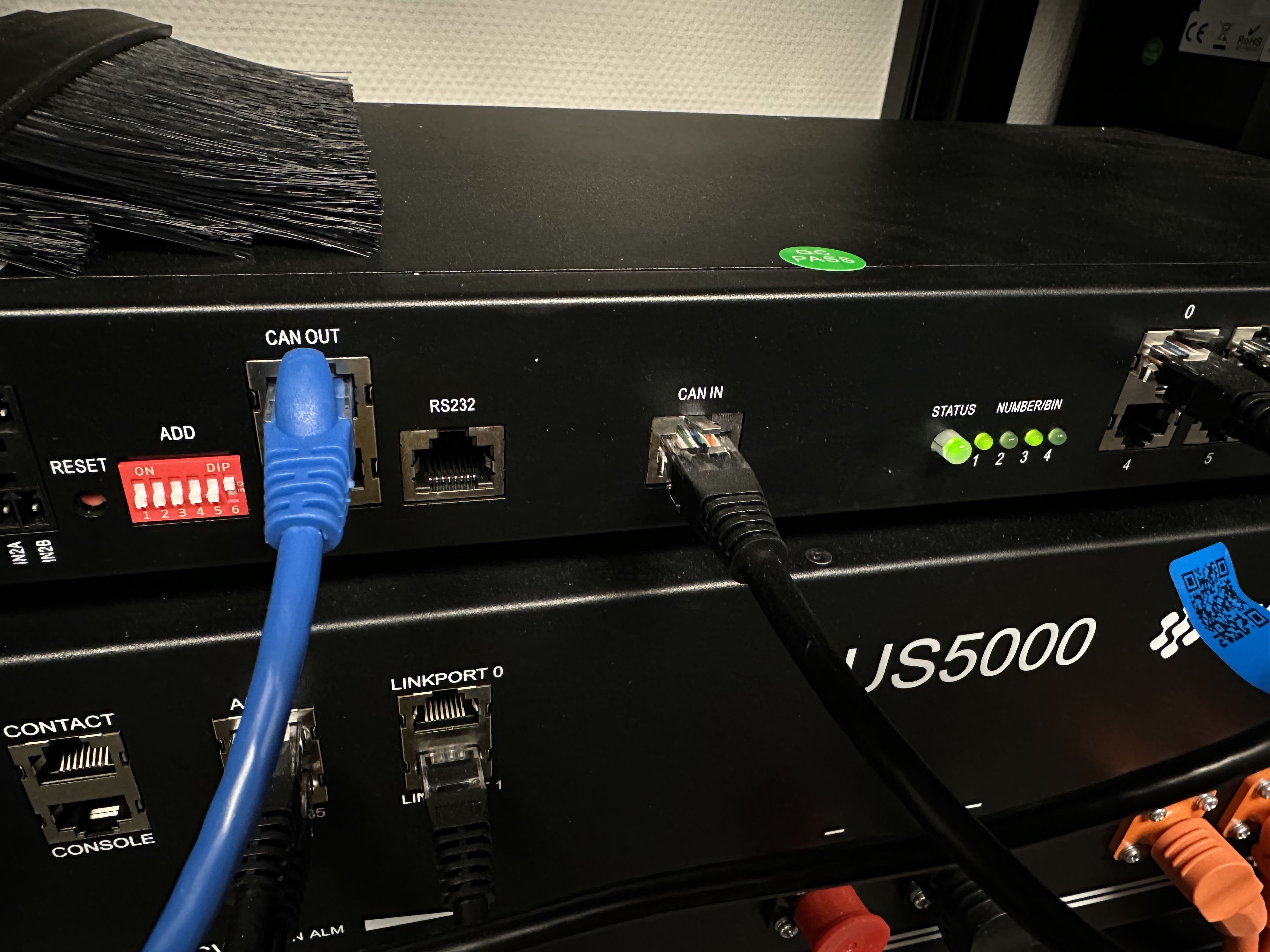
LV Hub: DIP: only the last one up. CAN IN to 0. Batteries on 1.

img-3722.jpeg


First (master) battery on 0100, but as the DIP switch is upside down, that shows as up up down up.

img-3723.jpeg

This is important (make or break)! The A/CAN to port 1 on the Hub uses the BATTERY cable, with some of the pins disconnected. The B/RS port of the master string goes to the next A/CAN, which takes another cable from B/RS to A/CAN of the next string, and so forth. These use regular ethernet wired cables (all pins connected).

img-3724.jpeg

So only the master battery (first string) has BATTERY cable with disconnected pins on A/CAN, all others have just a regular ethernet cable to the next string:

img-3726.jpeg

Of course all batteries in a string use the link ports to connect the next batteries in the string:

img-3725.jpeg

The above only worked after updating the LV Hub and batteries to the latest firmware with a Cisco Console cable where I put on a new RJ45 plug as per https://www.youtube.com/watch?v=qj07v10E4XA

End result 36 of them, three phase setup. Very happy with it.

img-3728.jpeg

img-3730.jpeg

img-3729.jpeg


img-3722.jpeg (1.6 MiB)
img-3723.jpeg (2.6 MiB)
img-3724.jpeg (2.1 MiB)
img-3726.jpeg (2.5 MiB)
img-3725.jpeg (1.9 MiB)
img-3728.jpeg (2.6 MiB)
img-3730.jpeg (3.0 MiB)
img-3729.jpeg (2.7 MiB)
2 |3000

Up to 8 attachments (including images) can be used with a maximum of 190.8 MiB each and 286.6 MiB total.

janvi avatar image
janvi answered ·

@Wietse Wind I can hardly recognize any diffrence to my cabling and dip switch setup. One exception: Assume the blue cable between LV Hub and Cerbo GX is genuine Victron type A. On my cable there is a white shrinking tube what indicates the Pylon end. Opposite end belongs to Victron. My type A cable is not working with switched ends and the reason therefore is obviously clear after examination of the pin assignements. I simply cannot see the white shrinking tube in your photo.

All my HW is new and here are my versions indicated by battery view.

version.pnglvhub.pngImage Caption


version.png (236.1 KiB)
lvhub.png (92.2 KiB)
2 |3000

Up to 8 attachments (including images) can be used with a maximum of 190.8 MiB each and 286.6 MiB total.

Wietse Wind avatar image
Wietse Wind answered ·

@Janvi Guess it's either your A/CAN of master to port 1 @ LV Hub cable, your LV Hub » Cerbo cable or the DIP settings on your LV Hub.

I assume your LV Hub to Cerbo cable is a standard Victron cable? Note: Victron Type A (!)

And your A/CAN (master battery) to LV Hub: that needs to be the one with pin 1-3 disconnected. In case of doubt: I have plenty of those cables, lmk if you want to make sure it's the right one and I'll send you one per DHL Express.

2 |3000

Up to 8 attachments (including images) can be used with a maximum of 190.8 MiB each and 286.6 MiB total.

janvi avatar image
janvi answered ·

Thank you @Wietse Wind for asking again for the cable between LV Hub and 1st group Master. I checked numerous times to have pins 4,5,6,7 connected and pins 1,2,3 disconnected. This is correct although another user reported his setup works with full connected 1:1 patch cable without any problems.

The trick of this connection is the shielding braid of the cable. The shielding needs to be connected at both ends as a 9th conductor. Some CAT5E plus are completely of plastic, other CAT5E plugs have a metal case what is not connected and a 3rd group of CAT5E cables have a connection between the plug shieldings. Genuine Victron Type A cable to Cerbo GX does not have this shield connection. CAT6+ patch cables seems to have this 9th shield connection by default.

Pylontech LV Hub does not have any PE screw at the painted sheet metals. All sockets are galvanically isolated and socket shieldings have small capacitive connection to PE. Therefore it seems to be a strong common mode error what kills my communication between Group 1 Master and LV Hub. Following behaviour can be reproduced very reliable:

- cable without 9th shield connection: LV Hub blinks red

- cable with 9th shield connection: LV Hub blinks green recognizing 2 groups

As this seems already a partitial success, Cerbo GX recognition is still limited to 17 batteries instead 16 without LV Hub. The Group 2 master occasionally reported „address allocation error“ and went into locked state with red LED. All battery Dip switches are up, except Group1 Master where No2 is down after 3 beeps.

What exactly is your boot up sequence of all batteries ? Assume, my remaining problem is with automatic address assignment for the devices before the 3x beep sounds.

1) Do you use the red reset pusbutton or the black toggle switch to boot up the batteries ?

2) What is your sequence of booting the batteries ?

a- from Master to neighbour slave

or from last slave to master of the group ?

b- group 1 first followed by group 2 until last group

or last group first and first group last ?


dscf6832.jpg


dscf6831.jpg

screenshot-from-2023-09-26-09-40-34.png


3 comments
2 |3000

Up to 8 attachments (including images) can be used with a maximum of 190.8 MiB each and 286.6 MiB total.

fenne avatar image fenne commented ·
I have the same problem. where can i find a cat6+ cable. i find cat 6 and cat 6a cables but no cat6+.
0 Likes 0 ·
Rob Duthie avatar image Rob Duthie fenne commented ·
Cat 5 is fine and works OK no issues
0 Likes 0 ·
fenne avatar image fenne Rob Duthie commented ·
Ok nothing works in my case. i guess i will have to sell the hub. id o everything as it is shown here. i already had contact to pylontech service. the connection between hub and master battery simply doesn´t work although i have the right dip position and the right cables (groups connect to each other). i´m simply fed up with the pylontech hub. without hub 16 pieces of the us 2000c work.
0 Likes 0 ·
janvi avatar image
janvi answered ·

There are more and more doubts about the Pylontech brand. The dealer from where I purchased the LV Hub is completely blank faced in any matters of Pylontech support and asked me to make a YT video about my problem!

Here you see, what happens if I remove the cable between LV Hub and battery stacks. Exactly happens nothing for a long time. LV Hub goes on blinking green communication LED and displays two groups or stacks. The Cerbo stops operation within a few seconds if removing the type A cable. If there is a LV Hub without connection to battery, operation goes on with frozen and wrong values for a long time. This is not only a bug but dangerous with a current of kiloamperes at the 48V busbar. Things like this, urgently need explanations by Pylontech itself.

dscf6845.jpg


dscf6845.jpg (723.5 KiB)
2 comments
2 |3000

Up to 8 attachments (including images) can be used with a maximum of 190.8 MiB each and 286.6 MiB total.

mschallwig avatar image mschallwig commented ·

Hi janvi,

have you found a solution now?

0 Likes 0 ·
janvi avatar image janvi mschallwig commented ·
No solution and no reaction from direct support request to Pylontech for 2 weeks now
0 Likes 0 ·
janvi avatar image
janvi answered ·

Hello all, finally I am happy to report success. Everything is working according to the manuals descriptions. I had a stupid problem with the last group last link cable. It was connected to RS485 instead Link Port what caused the occasional Address Allocation Errors.

Assume all, boot up procedure of groups and DIP switch changing while boot up between making patch connections are annoying and I have to practice this several times.

screenshot-from-2023-10-26-11-31-33.png


2 |3000

Up to 8 attachments (including images) can be used with a maximum of 190.8 MiB each and 286.6 MiB total.

nick-d avatar image
nick-d answered ·

Hello all, just read the whole thread and tried almost every suggested solution except flashing my lv-hub and batteries.
So the thing is: I'm trying to configure lv-hub with a single battery (master without any slave batteries) in order to test the setup and getting constantly red light.
I'm using the full 8-pin straight cable between CAN-IN and port 0 at lv-hub
native pylontech bat-to-inverted cable between the battery and port1 on lv hub.
also tried any crazy battery address pin combinations (0100,0010)and none of them works for me.
Also, i can't hear the beep on my single battery and i have to press red button in order to start it (run starts blinking).
Is it a legit approach to test the lv-hub, or i need a battery array in order to test it properly?
any suggestions?

1 comment
2 |3000

Up to 8 attachments (including images) can be used with a maximum of 190.8 MiB each and 286.6 MiB total.

Rob Duthie avatar image Rob Duthie commented ·
You need the battery array connected so the data can flow etc.!
0 Likes 0 ·
pip895 avatar image
pip895 answered ·

Slightly similar to the previous poster.

I have a setup working with 16 Pylontech US3000c batteries all working fine no issues. We have two more batteries we want to install so I have purchased a LV Hub and I have set it up to work as two stacks of 9 batteries (3 batteries per cable pair & three cable pairs per stack). We start with the system powered down and then follow the steps outlined above i.e.:-

  • Disconnect LV HUB from master battery.
  • Boot up every single battery, sequence 1-2-3 .... to the last battery.
  • Then you should hear an alarm buzzer which goes like this " bip, bip, bip" (three times). That means every battery is online and connected.

We turn on every battery with the switch then press the red button and every battery powers on in sequence - the second stack starting up when the first stack is about half way through but no buzzer ever sounds! -all the batteries seem to power up fine though. This happens every time and as the LV Hub isn't even connected at this point, it doesn't matter what we do with the dip switches or what software is in it, obviously. HELP where am I going wrong?

2 |3000

Up to 8 attachments (including images) can be used with a maximum of 190.8 MiB each and 286.6 MiB total.

pip895 avatar image
pip895 answered ·


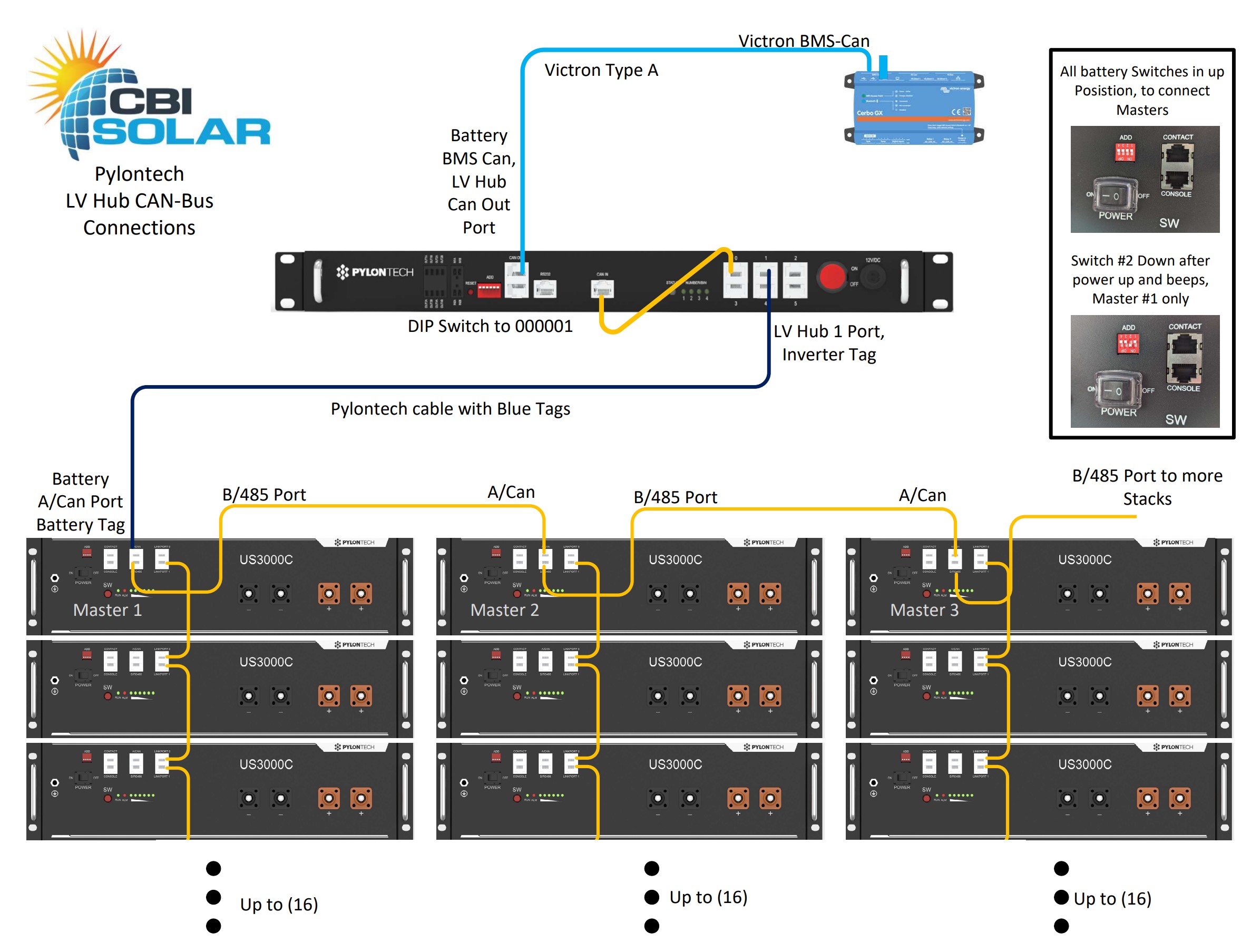
I thought I would post my solution to this problem as none of the above seemed to work for me. I used the nice clear diagram posted by Mark Whittaker shown below :-


hub.jpg


I then followed the instructions for two groups:-

  1. Make sure all batteries off
  2. Make sure LV hub is off
  3. Make sure inverter and Victron BMS is off
  4. Make sure ALL batteries have DIP switch set to 0000. Opposite way to the ON
  5. Change the DIP switch of only the master in the second group to be 0100
  6. Turn on all batteries
  7. Press SW on the master in group 1
  8. All batteries should turn on including 2nd group (3 beeps from master!)
  9. Turn on LV Hub, the 2 LED should light for two groups. (which they did)

Turn on inverter(s).

And it all worked!


hub.jpg (538.1 KiB)
2 |3000

Up to 8 attachments (including images) can be used with a maximum of 190.8 MiB each and 286.6 MiB total.

Pavel Richter avatar image
Pavel Richter answered ·

Hello,
I read it several times.
My installation has 32 pcs US2000C + LV-HUB.
I plugged everything in, turned it on according to the instructions ... beep beep beep ... everything works.
Cerbo FW 3.14 shows a max charge discharge current of 800A which is fine.
But there is no detail item at all where the cell voltages, temperatures can be seen... I miss that.
I have direct from pylontech FW for US2000C. I haven't updated yet.

I need an advice. Should I update the batteries or the LVHUB or both?
I don't like to update things that work.
How to update LVHUB? everything has to be plugged in, all batteries? So that something doesn't go wrong.
1) I connect to LVHUB using battery view
2) upload a BIN file? or zip file?

Couldn't the LVHUB update process mess up the batteries somehow?
If someone could write me a step-by-step procedure for a successful update, I would be grateful.

thank you very much

2 |3000

Up to 8 attachments (including images) can be used with a maximum of 190.8 MiB each and 286.6 MiB total.

Rob Duthie avatar image
Rob Duthie answered ·

Hi

Yes you need to update the battery firmware to show the data for the battteries on the Cerbo.

Updating the battery it self will be fine. You have to udate each battery separately.

There software will guide you thought it OK, Battery View Ver 3.0.29 using a the bin file provided by Pylontech.

Why doesnt the installer do it for you?

Regards

Rob D

NZ

2 comments
2 |3000

Up to 8 attachments (including images) can be used with a maximum of 190.8 MiB each and 286.6 MiB total.

Pavel Richter avatar image Pavel Richter commented ·

Hello,


Thanks.

I am an installer but this is my first installation with lv-hub


Batteries have older FW. If I only connect the battery to the cerbo, I can see the details of the battery.

I think this is a problem in FW lvhub.

but upgrading the batteries is not a problem. I have FW directly from pylontech.


It's just not clear to me how to upgrade lvhub so it doesn't affect the batteries.

I will connect to RS232 to lvhub and send FW. This should only upgrade lvhub. That's my guess.


It is absolutely tragic that pylontech does not have procedures and detailed information about downloadable FW on the website.

0 Likes 0 ·
Rob Duthie avatar image Rob Duthie Pavel Richter commented ·

HI

I have the details on how to do it, send me a email,

raduthie@gmail.com

0 Likes 0 ·
Alex Pescaru avatar image
Alex Pescaru answered ·

Hi All,

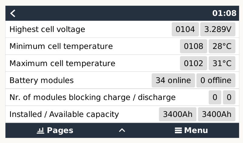
On Cerbo, besides @Wietse Wind on the message from Jul 12 2023, who has on the "Available capacity" the same value as the value on "Installed capacity" 3400Ah / 3400Ah, all others have on the "Available capacity" only two dashes. "--"

Why is that? What to do for the "Available capacity" to show the real/correct value?

Thank you!

Alex

2 |3000

Up to 8 attachments (including images) can be used with a maximum of 190.8 MiB each and 286.6 MiB total.

Simon Hackett avatar image
Simon Hackett answered ·

Hi all,

I have just finished commissioning a 40 x US5000 system with an LV-HUB connected to 6 x Quattro 48/15000's in a three phase ESS system with 100kWp of AC solar.

I've learned a lot in the process - which involved a full day of 'head scratching', and I wanted to write down what I have learned, here an an effort to save others some time, if I can!

I'm going to start with this post , to explain, in detail, what the LV-HUB actually does, and how it does it, because a full understanding of that can really help with debugging these systems.

In the next post after this one, I'll relate what I learned when I commissioned my 40 x US5000 system (and this in turn lead to the understanding of how the LV-HUB works that I'll relate here!).

To start with, there is a key point to appreciate about CANBus BMS operations with a Victron Energy GX (or indeed with any inverter/charger that uses the CANBus BMS protocol).

The upstream system (here, the GX) expects there to be just a single CANBus BMS device, providing BMS (battery system) data to the GX. Each second, over that CANBus port, the single BMS on the CANBus port updates the GX with information about the operational status of the battery array, via that (industry standard) protocol.

The same CANBus port on the GX can also talk to other things on the same CANBus (for instance, Victron Energy CANBus MPPTs)...and there can be multiple of those... but there must be just one CANBus BMS talking to the GX - the protocol does not allow for the presence of multiple CANBus BMS's

Over on the US5000 side, up to 16 (officially) US5000's can be daisy-chained to each other, and they will function as (and represent to the GX as) a single CANBus BMS, with the CANBus BMS signal coming out of the A/CAN port on the master US5000.

The master unit in the stack talks to the other units in the same stack (via the LINK ports), and aggregates module data for all of the batteries into one CANBus BMS data stream for the GX. Easy.

For bigger systems, you need to break the US5000 setup into multiple stacks (the LV-HUB documents call these stacks 'BINS' or 'PILES', but I'll call them 'stacks' here!)

Each stack separately generates a CANBus BMS protocol stream from the master (top of the stack) unit concerned.

What we need, then, is a way to aggregate those multiple CANBus BMS protocol streams into a single one that represents, literally, the 'totals' across all downstream CANBus BMS units. The 'adding up' of information inside a stack has to be done again, at this higher level - adding up all of those 'totals' to give us a single overall BMS status stream for all the US5000 modules.

Well, of course, that is what the LV-HUB does.

On the "CAN IN" side, the LV-HUB listens to multiple CANBus BMS units (each being the master for a stack of US5000s).

That 'listening' happens over a single physical CANBus network... and it is a single CANBus network, really, however you connect the stacks to the LV-HUB.

Key point: The cluster of ports on the right hand side of the LV-HUB is 'just' a passive CANBus aggregation hub.

That cluster of RJ45 ports, labelled 0,1,2, 3 etc... it doesn't matter which cables go into which ports, it's just like an old school ethernet hub. That's why there is a documented short patch lead from port 0 of that hub into the CAN IN port - to connect that passive hub, physically, to the CAN IN port.

Importantly, this also means that use of that CANBus hub at all is in fact optional. You can just plug a CANBus cable directly into the CAN IN port and ignore the CANBus hub ports entirely.

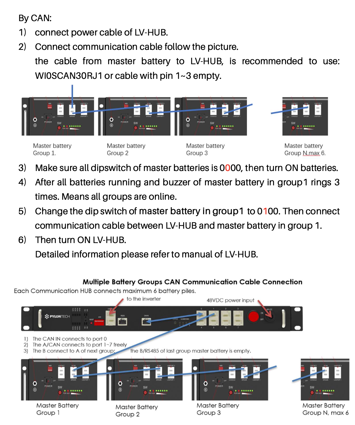
Pylontech documents, in various spots, show two different ways to connect the CANBus signals from multiple US5000 stacks together, and the next key point is that both methods are in effect identical.

Here are the two ways that different bits of Pylontech documentation show us:

Method 1:

- Connect each US5000 stack into a separate port on the CANBus hub on the LV-HUB unit, and connect a patch lead from port 0 of the CANBus hub into the CAN IN port

Method 2:

- Daisy-chain the US5000 stacks directly, connecting the B/485 port on the master for the first stack to the A/CAN port on the master for the second stack, then daisy-chain the same way to connect over to each US5000 master unit in succession.

Method 2 is the preferred one for US5000's in particular, and I assert that point because the image showing that method (the image I have attached below) comes from the US5000 manual (not from the LV-HUB manual), and that is the only way the US5000 manual proposes to do it.

So: Follow the instructions in the US5000 manual to connect up that system and initialise it. Once you get it right, the stack 1 master will beep 3 times - and this confirms that the stack-of-stacks is all up and running happily.

** Note the US5000 dip switch is upside down ** - this can be super confusing as the instructions on setting this switch have to be 'inverted' to be accurate... see detailed notes in the post after this one ***

The only point I'd make about the attached diagram is that - as you can see - there is a patch lead from CAN IN to port 0 of the LV-HUB CANBus hub, and then a cable out of port 1 of that hub, down to the stack of US5000 modules.

You don't need it.

You can connect the US5000 stack master directly into the CAN IN port on the LV-HUB and forget about the RJ45 ports on the right hand side of the LV-HUB entirely. I have done this - it means one less cable, and one less bit of 'religion' about what that CANBus hub does (i.e. really 'nothing').

So what I've done is exactly as per the attached diagram, except my CAN IN port is a single cable that direct connects to the 'top left' US5000 A/CAN port in my battery stack.

So there you go - now you know how an LV-HUB really works, and how best to wire it to a stack of US5000 units.

There are some 'gotchas', though - see the next post :)


us5000-stacks-wiring.png

j


2 |3000

Up to 8 attachments (including images) can be used with a maximum of 190.8 MiB each and 286.6 MiB total.

Simon Hackett avatar image
Simon Hackett answered ·

Now I'll relate what I learned in the process of commissioning my 40 x US5000 system, in the hope that it helps others.

Lots of points here, in no particular order:

  • You have to make sure the LV-HUB is running version 1.8 (or later, I guess, but that's the latest right now). I wasted a lot of time assuming my 'new-in-box' LV-HUB would already be running the version 1.8 firmware (released in 2022). But it was actually running V1.7!
  • First consequence of not running LV-HUB version 1.8: The 'Detail' field on the BMS sub-menu for "Pylontech battery" on the GX (showing module-level information) is absent. That absence of the "Detail" sub-menu is the simplest way to be sure you need to upgrade the LV-HUB firmware
  • Second consequence of not running LV-HUB version 1.8: If you connect more than 32 x US5000 modules to the GX, then the BMS data sent to the GX becomes corrupted (charge voltage and charge current limit show up on the GX as '---', and the GX operation confused). The GX shows the BMS as being present but it does not actually use it. DVCC does not auto-select, and it is just... bad.
  • Hence, to repeat this: You must make sure the LV-HUB is running 1.8, and if the "Detail" sub-menu is absent from the BMS "Pylontech battery" menu on the GX, you are not running 1.8 and you need to get it upgraded to avoid wasting your time and money (as I did :) ).
  • About question of how to set the dip switches on the LV-HUB (very first post in this thread): As Matthijs noted above, the right way is 'as per the manual' - right-most DIP switch 'up', all others down, i.e. 000001.
  • Using 000111 does 'work', but it changes the way the BMS signals to the GX, and that changed signalling means the GX no longer recognises that it is a Pylontech BMS, and no longer auto-configures DVCC properly.
  • If you use 000001, the GX (on the DVCC page) shows DVCC as 'Forced On' (and you want this to be the case!!). If you use 000111, the BMS shows up on the GX with the name "PYLON" (not "Pylontech battery"), and DVCC is not forced on. The right answer really is 000001..and that '1' is just switching in the CANBus terminator built in to the LV-HUB so that the CANBus cable to the GX works properly in electrical terms.
  • The best reference for wiring the LV-HUB systems up to US5000's is the US5000 manual. It shows just one method to do it, and not the LV-HUB manual, that shows multiple methods, none of which are in any way preferable to that 'best' way in the US5000 manual.
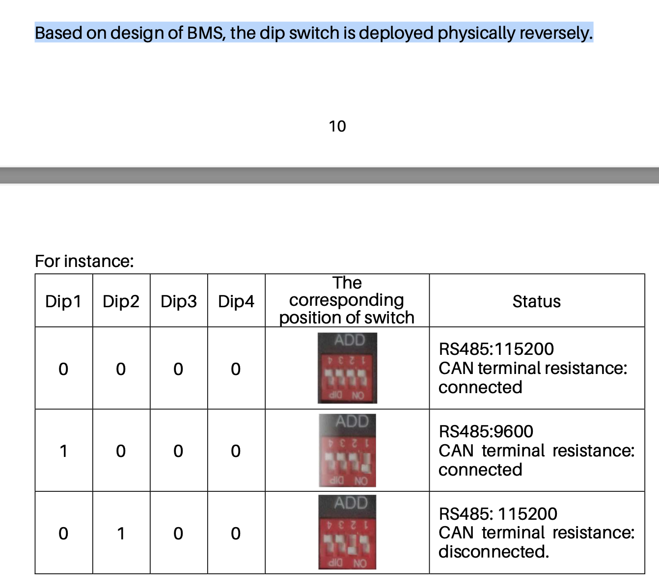
  • The DIP switches on the US5000 units are upside down. This is documented in the US5000 manual, but the references to switch settings in that manual (e.g. "Change the dip switch of master battery in group1 to 0100") actually means you need to physically move the second DIP switch from the right to the lower position... because that DIP switch is upside down! The best reference to this is a page in the US5000 manual that contains both a photo and an explanation of the switch settings. I have attached a copy of that to this post. If you don't appreciate this point, and move the second switch from the left, then stuff won't work as you expect it to!
  • Note from the attached image, too, what the DIP switch on the US5000 actually does - it just switches the CANBus terminator in and out. All switches off (up!) means the terminator is connected. DIP2 (second from right!) pushed down means the CAN terminator is disconnected. The instructions in the US5000 manual for how to configure the stack of stacks is accurate - just follow it in sequence, noting that confusing thing about the DIP switches 'as above' and 'it all works'.
  • If you do not switch DIP2 on (down!), what happens is that the CANbus cable signal can become noisy, and the LV-HUB picks up on the noise and in response, as a protective mechanism, it limits the maximum BMS charge rate to 20A per US5000 module. So if you want to get the full charge rate available via the LV-HUB, you need to make sure that DIP position is correct.
  • On the other hand, note that because it is just switching a resistor in and out, you don't need to 'reboot' anything if you get the switch position wrong - just 'fix it' - and - as the documentation says, just move DIP2 down on the US5000 with the cable link back the LV-HUB, leave all the others unchanged.
  • In summary overall - the US5000 documentation is right, and it works - once you appreciate the absolute confusion possible because that DIP module is physically upside down :)

Last things... these are some more things I have learned - and some corrections I believe are needed to the Victron Energy page - about how to configure ESS to work with this sort of system:

  • The ESS Assistant ‘sustain’ voltage on the Victron information page is, in my view, wrong. It tells you to set a sustain voltage of 48V, but it really needs to be 45V.
  • If you use 48V, the system will mysteriously stop discharging at 48V (obviously), and switches to 'Sustain" mode, making further discharge impossible. This happens at around a 20% SoC on my systems, and it means you can't get the SoC any lower than that on the array.
  • Hence... to 'dig deeper' than 20% (and the US5000 says you can use 95% of the battery if you are using a working BMS connection), then you must reduce the ESS Assistant sustain voltage setting to 45V. Note that the Pylontech US5000 data sheet indicates the minimum operational voltage is actually 43.5V, so a 45V sustain level really is fine here.
  • The Victron Energy Pylontech page also says: "“Discharge Current Limit set to 0A at 47V, inverter will turn off.” - which appears to conflict with the previous point... but in my direct operational experience, this does not happen, and 45V works fine.
  • Perhaps the older/smaller models of Pylontech battery (also covered by Victron Energy on the same page) do have this limitation, and maybe you need to use 48V for them... but for the US5000, you definitely want 45V here, unless you don't mind never using the bottom 20% of your battery energy, ignoring the ESS "MinSoC" setting for any voltage below 48V.


I sincerely hope his helps others to save some of the time that it took me to learn these points :)


canbus-terminator-dip-switch.png


2 |3000

Up to 8 attachments (including images) can be used with a maximum of 190.8 MiB each and 286.6 MiB total.

Related Resources

Victron Pylontech battery compatibility guide

Additional resources still need to be added for this topic