hey,
how can I control the relays via Venus OS?
- Home
- Anonymous
- Sign in
- Create
- Spaces
- Grafana
- Node-Red
- Unsupported topics
- Questions & Answers
- Modifications
- Communauté francophone
- Deutschsprachiger Bereich
- Preguntas en Español
- Explore
- Topics
- Questions
- Ideas
- Articles
- Badges
question
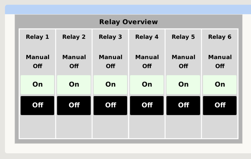
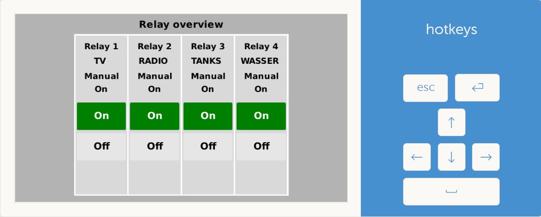
relay overview Venus OS
There is some people making and using this deisgn i did some time back.
Regards
Rob D
NZ
There is actually influences prior to config.txt is read:
First, the chip has default GPIO configurations that are applied when the chip receives a reset. Depending on the GPIO, a pull-up or pull-down may be in effect at this time until the next step.
Next a device tree overlay is applied during the initial phases of the boot process. This too can redefine GPIO configurations and state.
Then as mentioned in the original post, config.txt can reconfigure GPIO ports.
Then on to gpio_list.
If you are asking where this overview page comes from, it's part of my GuiMods package:
https://github.com/kwindrem/GuiMods
What do you need for that?
Besides manual control, Relay 1 can be set to be controlled by conditions within Venus such as generator start/stop, tank pump or alarms. As of Venus v2.80~36 the relays can also be controlled by temperature sensors. All these setups are from the standard Venus menus, starting with the Relay menu to select the function for each relay. Then, additional setup may be needed in the menu for that functionality (e.g., the Tank Pump menu allows selection of which tank and the start/stop levels, or the Temperature Sensor menu inside the Relay menu).
yes I use a pi3 - and maybe I want to use some relays not all 6 relays but maybe two.
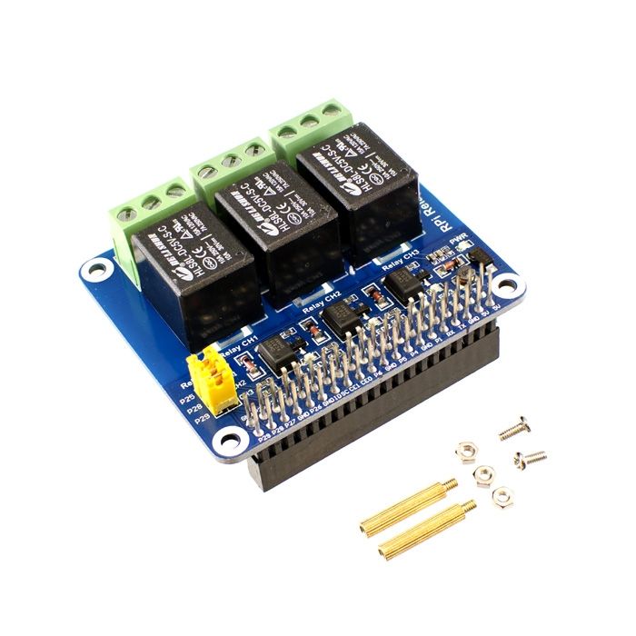
like this head?:
I know some relay hats use active low which creates issues with Venus OS since there is no way to change the polarity.
Search around on the forum for more help or relays for Venus. Sorry, it's just an area I've never looked into.
Note that you must remove relay and digital input definitions such that they are consecutive beginning at 1. That is removing relay 3 won't work.
GPIO usage is not easy to manage and it takes a lot of research before selecting hat devices. It is easier to use USB based devices CANbus adapters and now with RemoteGPIO, relays and digital inputs than to use Raspberry PI hat modules.
I use this:
https://de.aliexpress.com/item/1005001903120199.html?spm=a2g0o.productlist.0.0.53a4a47cl9KvXt&algo_pvid=2b671b94-7126-44f2-b2cc-92a2f81d8117&algo_exp_id=2b671b94-7126-44f2-b2cc-92a2f81d8117-9&pdp_ext_f=%7B%22sku_id%22%3A%2212000018071399453%22%7D&pdp_pi=-1%3B1.95%3B-1%3B-1%40salePrice%3BEUR%3Bsearch-mainSearch
it has 6 relays and you can set the trigger H/L separately.
With QML coding experience you could customize the overview exactly how you want it.
I use this one with my Pi 3+: https://www.amazon.com/gp/product/B072XGF4Z3 and it works well. The only thing I had to do is modifying the "etc/venus/gpio_list"
#### modified for use by the RpiGpio package on Raspberry PI platforms ONLY

# This is a list of gpio pins, set by the script /etc/rcS.d/S90gpio_pins.sh
# They are documented at: https://github.com/victronenergy/venus/wiki/bbb-gpio
# Format: <pin_number> <direction: in/out> <name>
#
# The <name> part is used to create an symlink in /dev/gpio.

# relays are active HIGH

# Relay 1   Pin 40 / GPIO 21 CHANGES FOR RELAY HAT: -> GPIO 4
4  out relay_1

# Relay 2 Pin 11 / GPIO 17 CHANGES FOR RELAY HAT: -> GPIO 22
22  out relay_2

# Relay 3 Pin 13 / GPIO 27 CHANGES FOR RELAY HAT: -> GPIO 6
6  out relay_3

# Relay 4 Pin 15 / GPIO 22 CHANGES FOR RELAY HAT: -> GPIO 26
26  out relay_4


# Relay 5 Pin 16 / GPIO 23
23  out relay_5

# Relay 6 Pin 18 / GPIO 24
24  out relay_6


# these have pull UPs
# Digital input 1   Pin 29 / GPIO 05
5   in digital_input_1
# Digital input 2   Pin 31 / GPIO 06 CHANGES FOR RELAY HAT: -> GPIO 17
17   in digital_input_2


# in stock code these have pull DOWNs
#### modified to pull UPs by the GPIO overlay that is installed as part of this package

# Digital input 3   Pin 33 / GPIO 13
13  in digital_input_3
# Digital input 4   Pin 35 / GPIO 19
19  in digital_input_4
# Digital input 5   Pin 37 / GPIO 26 CHANGES FOR RELAY HAT: -> GPIO 27
27  in digital_input_5

#### Gracefull shutdown input
#### Note this input is NOT added to the available I/O used by Venus OS !!!!
# Pin 36 / GPIO 16
16  in digital_input_6
Hello,
that works. thanks for that.
can it be that from time to time it adjust again or when something is updated?
can you save the setting permanently?
A venus firmware update will overwrite the changes to the gpio_list file. Consider using my RpiGpioSetup package along with SetupHelper to keep the changes. RpiGpioSetup now supports a custom gpio_list file.
After the update to 2.80 the relay overview area is empty.
Under settings I can't find the item relay anymore
what happened? :(
Is RpiGpioSetup shown as installed in PackageManager?
Are you running the large version of Venus OS. If so, there's an update to SetupHelper that fixes an install bug for all packages.
Otherwise, hard to say without logs.
Hi Kevin,
can you please give me a little information how the gpio_list file in the RPIGGpioSetup should look like or how it can be setup? There is a section in "/data/setupOptions/RpiGpioSetup" called "optionSet". I'm a little bit confused how to handle it to keep the settings.
Thanks!
The RpiGpioSetup package contains a default gpio_list file. That file should work when using the GPIOs on the 40-pin header, but if you are using a relay HAT, etc, they may not be correct.
You can copy that gpio_list file to /data/setupOptions/RpiGpioSetup then edit it to change the assignments. The package will look for /data/setupOptions/RpiGpioSetup/gpio_list first before installing the default one.
The assignments you make in this file will depend on the harware you are trying to use for Venus digital inputs or relay outputs.
The custom gpio_list file is independent of the optionsSet flag file.
"optionsSet" is a file that tells the setup script that the options have been set by the user. Once they have been set, they persist in the setupOptions directory and survive a Venus firmware update. If the options have been set, the setup script will be run on the first boot following a Venus firmware update. If the package requires options to run the setup script without user interaction, as happens during during a reboot following a Venus firmware update, the setup script will not reinstall the packages. if the optionsSet flag file is not present. Most of my packages don't require any setup options, so the setup script will skip the optionsSet check. At this point I think only package that requires command line options is VeCanSetup.
RpiGpioSetup is an excellent package Kevin, Thank you for your work. I have it working with Rpi 4 (1.4) with the 8 channel waveshare relay board. Is it possible to switch the waveshare relays on the Rpi with your package installed using Node-Red?
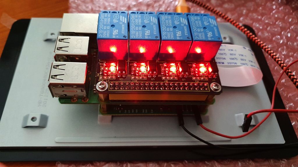
The plug-on relay board described by "itsme" has 4 relays. Installation is easy and works great so far.
My Pi 3b+ my venusOS v2.86 with SetupHelper + RpiGpioSetup.
"Call the gpio_list file for the relays in e.g. putty:
nano /etc/venus/gpio_list
and delete the list.
Copy the new modified list from "itsme" and paste it in place
Ctrl X to confirm
Ctrl Y for Yes
Then confirm the query with Enter"
Finished.

The relays become noticeably warm during continuous operation. You now have to prove yourself in practice.

Thanks go to "itsme" for his excellent work.
And that he modified the "gpio_list" and made it available here tailored to the relays.
Is there an option to use all 4 relays with a temperature condition? I can only set conditions for Relay 1 & 2.
Hi can anyone help me with my 3 relay when i turn it off it turn on and when i turn it on it turn off.
thank you

The problem with relays that activate with an active low signal on the GPIO pin is that the earliest opportunity to invert the pin's logic is in the middle of the boot process. That means that the relays will activate for a few seconds when the system reboots.
Your best bet it to select a hat that activates on an active high or better yet use the Dingtain family of relay/digital input devices and the RemoteGPIO package. These boxes can connect via ethernet/wifi or USB using an RS-485 to USB adapter.
https://github.com/Lucifer06/RemoteGPIO
Hi,
if some people end up here because they are having an issue where during the boot/reboot phases, there GPIO pin go up or down for a few second and this create an issue for them.
Jump to #SOLUTION if you want to avoid the explanation.
Example: For me it's connected to a generator startup and having it going up or down will start the generator during reboot, which you guess it not what I wanted.
Here is my non educated understanding. There are 3 layer which can influence the configuration of the GPIO pin. The Raspberry layer, the venusOS layer, and the plugin layer.
During the boot sequence each of them intervene in this order 1 Raspberry, 2 venusOS, 3 plugin(if any). And therefore you can have your GPIO pin change 3 time of state/config during the boot.
The Raspberry layer is set with the file config.txt with the part related to the GPIO pin documented here https://www.raspberrypi.com/documentation/computers/config_txt.html . You will find the file here /u-boot/config.txt or you can do a
find / -name config.txt
In this file you can change some of the value of your GPIO pin at the very beggining of the boot sequence, this is particularly useful if you are using a GPIO pin which normally is high or low and you want to have it the other way around. The GPIO pin 0-8 are high, remaining are low with exception, see the table at 6.2 page 102 https://datasheets.raspberrypi.com/bcm2835/bcm2835-peripherals.pdf.
So for example if you want to use GPIO pin 20, 21 it will be low by default during boot sequence and depending on you relay, low can mean active (you see a light), and you might now want this. For me it is not really an issue as the light is just slighly red and I don't think it's active, but depending on the relay if can be an issue. In any case, you would add this to your config.txt
gpio=20,21=op,dh
---
Then come the venusOS layer. The script gpio_pins.sh https://raw.githubusercontent.com/victronenergy/meta-victronenergy/master/meta-venus/recipes-bsp/gpio-export/files/gpio_pins.sh is called and it will read the content of the file gpio_list.
gpio_pins.sh is located at /etc/init.d/gpio_pins.sh or do a
find / -name gpio_pins.sh
the file gpio_list is located at /etc/venus/gpio_list
By default the script gpio_pins.sh seems to only do the assignment of the GPIO pin to the relays and to set the GPIO pin direction (input or output). This is why you pass just 3 argument in the file gpio_list which are:
gpio_pins.sh
PIN_NUM=$1
PIN_DIR=$2
PIN_NAME=$3
gpio_list
20 out relay_1
21 out relay_2
#SOLUTION
The solution is to correctly set your config.txt, please refer at the part about this above.
And then to modify the script gpio_pins.sh such as:
#!/bin/sh
### BEGIN INIT INFO
# Provides:          gpio_pins.sh
# Required-Start:
# Required-Stop:
# Default-Start:     S
# Default-Stop:
# Short-Description: Exports gpio pins.
# Description:       Exports gpio pins from config file /etc/venus/gpio_list
### END INIT INFO

#reads ${GPIO_FILE} and performs export_pin and set_pin_dir on each line
#GPIO_FILE should be in the format:
# <number> <in/out> <relay> <value:0/1> <up/down:0/1>
# <number> <in/out> <relay> <value:0/1> <up/down:0/1>
#
#
#for example:
# <number> <in/out> <relay>   <value:0/1> <active_low:0/1>
# 20       out      relay_1   1           1
# 21       out      relay_2   1           1

GPIO_DIR="/dev/gpio"
GPIO_FILE="/etc/venus/gpio_list"

export_pin() {
    echo $1 > /sys/class/gpio/export
}

set_pin_dir() {
    PIN=${2}
    FILE=/sys/class/gpio/gpio${PIN}/direction

    echo $1 > ${FILE}
}

set_pin_value() {
    PIN=${2}
    FILE=/sys/class/gpio/gpio${PIN}/value

    echo $1 > ${FILE}
}

set_pin_hilo() {
    PIN=${2}
    FILE=/sys/class/gpio/gpio${PIN}/active_low

    echo $1 > ${FILE}
}

create_link() {
    PIN=${1}
    FILE=/sys/class/gpio/gpio${PIN}

    ln -s ${FILE} ${GPIO_DIR}/$2
}

find_pin() {
    gpio=$(gpiofind "$1") || return 1
    set -- $gpio
    chip=$1
    offs=$2
    base=$(cat /sys/bus/gpio/devices/$chip/../gpio/*/base)
    echo $((base + offs))
}

set_pin() {
    PIN_NUM=$1
    PIN_DIR=$2
    PIN_NAME=$3
    PIN_VALUE=$4
    PIN_HILO=$5

    case $PIN_NUM in
        -) PIN_NUM=$(find_pin "${PIN_NAME}") || return 1 ;;
        +) PIN_NUM=$(find_pin "${PIN_NAME}") || return 0 ;;
    esac

    #echo "Setting gpio pin #${PIN_NUM}/${PIN_NAME} to ${PIN_DIR}"
    export_pin "${PIN_NUM}" || return 1
    set_pin_dir "${PIN_DIR}" "${PIN_NUM}"
    set_pin_value "${PIN_VALUE}" "${PIN_NUM}"
    set_pin_hilo "${PIN_HILO}" "${PIN_NUM}"
    create_link "${PIN_NUM}" "${PIN_NAME}"
}

check_compat() {
    cat /sys/firmware/devicetree/base/compatible | tr '\0' '\n' |
        grep -Eqx -e "$1"
}

mkdir -p ${GPIO_DIR}

sed 's/#.*//' ${GPIO_FILE} | while read num dir name value hilo compat; do
    # ignore incomplete lines
    if [ -z "$num" ] || [ -z "$dir" ] || [ -z "$name" ] || [ -z "$value" ] || [ -z "$hilo" ]; then
        continue
    fi

    if [ -n "$compat" ]; then
        check_compat "$compat" || continue
    fi

    set_pin "$num" "$dir" "$name" "$value" "$hilo" ||
        echo "Error configuring pin $num as $name"
done
You now have to pass 2 more argument in your gpio_list which are the value low(0) or high(1) and the active_low true(1) or false(0), please see this doc https://www.kernel.org/doc/Documentation/gpio/sysfs.txt for more info (search for /sys/class/gpio/gpioN/ ).
I hope it helps.
It's certainly not the best solution and a very adhoc one, it won't survive venusOS updates I guess, but it works for me.
Please don't hesitate to correct any incorrect statement or suggestions,
Best.
Related Resources
Additional resources still need to be added for this topic
question details
42 People are following this question.
