question

thomasw-1 avatar image
thomasw-1 asked

Eastron SDM630/SDM230 Modbus Energy Meter - community edition

======================================================================
Important Note
Support of SDM630 is continued in thread "Power Meter lib for Modbus-RTU-based meters from ABB, Carlo Gavazzi (Victron) and Eastron", the support of SDM230 is deprecated.

======================================================================

Update history

version 1.2

  • Support of legacy meter SDM630v1
    meter is only supported, if configured with baudrate >= 9600

version 1.1:

  • Support of SDM230
    (limited support - requires manual adaptation since device id is not supported on that device type - details see below)
    Thanks to Sergio for allowing access to his environment
  • Addition of supported product ID > shown properly in VRM

======================================================================

Hi All,

I like to share an implementation for support of the Eastron SDM630-Modbus and SDM230-Modbus v2 energy meters.
For any usage a donation to seashepherd.org with an amount of 5 USD/EUR/GBP or equivalent is expected.

Installation

  • copy Eastron SDM meters v1.2.zip -file into directory /opt/victronenergy/dbus-modbus-client and unzip it.
  • Add following bold-marked line into file /opt/victronenergy/dbus-modbus-client/dbus-modbus-client.py
    import carlo_gavazzi
    import Eastron_SDM630v2 (in case you use another meter version apply alternatively expression "Eastron_SDM230" or "Eastron_SDM630v1" instead of "Eastron_SDM630v2 ")
    import ev_charger
    import smappee
  • rename file /opt/victronenergy/dbus-modbus-client/dbus-modbus-client.pyc into /opt/victronenergy/dbus-modbus-client/dbus-modbus-client.py.orig
  • Since that file is not automatically compiled by VenusOS execute following bold marked commands in directory /opt/victronenergy/dbus-modbus-client
    python
    Python 2.7.18 (default, Apr 15 2021, 10:46:30)
    [GCC 9.2.0] on linux2
    Type "help", "copyright", "credits" or "license" for more information.
    >>> import py_compile
    >>> py_compile.compile ('dbus-modbus-client.py')
    >>> exit()
  • reboot VenusOS

  • SDM230 specific:
    Since SDM230 does not support device id, the device must be identified by serial id.
    In order to do so:
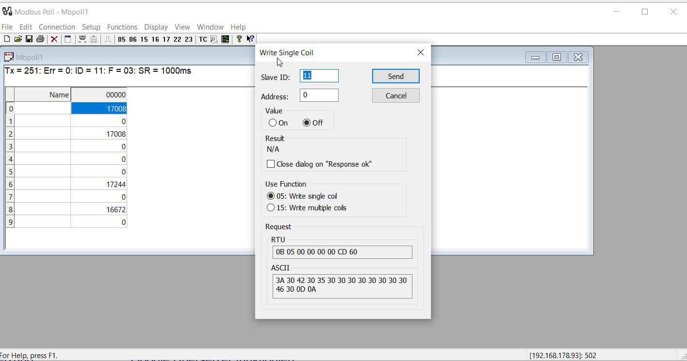
    • Read serial ID with holding register FC00 (unsigned int32) from SDM device
      result e.g. 20084317 (using a tool like e.g. modbus poll, iobroker or node red)
    • convert id into hex: 20084317 >> 0132 765D
    • take first 2 hex-bytes (0132) and convert it back into int (here 306)
    • configure that number in file Eastron_SDM230.py
      1627119618938.png
    • in case you use more meters in parallel multiply setting like in this exampe ID "84".

  • Go to "Settings" > "Modbus TCP devices" and perform a "Scan for Devices" or directy add a device via "Devices" > "Add" using relevant IP and ModBus ID and port. Last option is much quicker and also supports non-default unit-IDs.
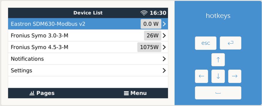
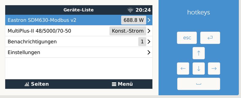
    A few seconds later the meter should appear in your main menu:
    1618745796225.png
  • Select in submenu "Setup" the usage as grid, pvinverter or generator meter
    1618745887195.png

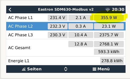
Main page screenshot

1618745382616.png

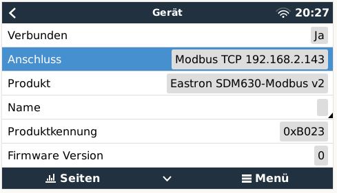
Device screenshot1618745459392.png
Comments:

  • Firmware register is not filled by devices (so no modul issue).
  • In above screenshots don't be misled by empty phases 2 and 3. In test environment I had only phase 1 connected. Phase config is dependent of device configuration.
    As soon as meter is configured with 1 phase support only, driver detects circumstance and excludes remaining phases.
    1618748013891.png

Important: The installation is not resistent for VenusOS updates. After an update to another release installation has to be repeated.

Exclusion of liability: Although the module has been tested in depth, I don't take any liabilty for any potential damage on your installation

Thanks to Victron for their open platform and especially for the support of Matthijs Vader.

Energy MeterModbus TCP
11 comments
2 |3000

Up to 8 attachments (including images) can be used with a maximum of 190.8 MiB each and 286.6 MiB total.

mvader (Victron Energy) avatar image mvader (Victron Energy) ♦♦ commented ·

Hi nice! One thing, I dont think its necessary to compile any file. Just replacing/modifying any .py file will automatically cause its pyc equivalent to be removed/replaxed by a freshly recompiled one. Thats just within Python to do that.

0 Likes 0 ·
thomasw-1 avatar image thomasw-1 commented ·

thomasw-1 avatar image

thomasw-1 beantwortet · vor 2 Sekunden


Indeed, all other modules get recompiled automatically, that however not. I am not a python expert. Therefore I habe no clue why not. Only difference to other files are the access rights.

1618763696628.png

0 Likes 0 ·
1618763696628.png (5.3 KiB)
stanhausc avatar image stanhausc commented ·

Hi @ThomasW.

Thanks for sharing your work.

I have the same job to do, however, for a KS-3000 meter.

Could you tell me from where you got this value:

productid = 0xB023 # id assigned by Victron Support

Is it a Victron default value? Should I use the same value for a different meter?


Would the id on my meter be 242?

id-slave-li.jpgimagem1.png

captura-de-tela-2021-09-13-203949.png


I changed the addresses for voltage, current, etc.

imagem2.png

captura-de-tela-2021-09-13-204123.png


But I didn't find in the manual, information about phase config, hardware. The firmware is bundled with the id, and I have no idea how to separate them.


But at first I need the Venus GX to recognize the KS-3000.

0 Likes 0 ·
thomasw-1 avatar image thomasw-1 stanhausc commented ·
Hi @stanhausc ,

the ID was assigned by Victron-Support. In case you publish your meter as well, you could raise a request for that. In the moment the id would not prevent your adaptation to work. Only in VRM another meter type would be shown.

In terms of meter identification you would have to study the supplier documentation, if there is a register that describes the meter type and makes id unique. A serial number is worst case, because it has to be changed for any individual implementation.
With my limited Spanish skills I reviewed briefly the documentation, however I could not identify a relevant register.

0 Likes 0 ·
stanhausc avatar image stanhausc thomasw-1 commented ·

Hi @ThomasW.


For the 02192288 serial of my Kron device for example, is the same conversion rule used in Eastron valid?


02192288 Dec > 2173A0 Hex > the first two bytes 21 73 > 8563 DEC, would that be it?

0 Likes 0 ·
jurekz avatar image jurekz commented ·
Have anyone connect SD630 direct to the Venus (Rasbppery) via RS485/USB converter?

Looking into code it shpuld work (however I'm not an expert).


0 Likes 0 ·
nostromo avatar image nostromo commented ·

Dear,

I wish to connect Eastron 630 V2 on my Multiplus II GX via adaptator RS485 to USB, I'm novice and how to start OS Venus adaptation to have 630 V2 recognised ?

Thanks in advance for help.

0 Likes 0 ·
fpfann avatar image fpfann commented ·

Hey Thomas,

followed your instructions and did every step you did. However I have a big problem, that my SDM230 is not communicating with my Raspberry I am running Venus OS on via USB/RS485 Cable. With my normal computer I could communicate via ModbusPoll.

Do you know any comman problems with the SDM230?

Thanks a lot!

0 Likes 0 ·
thomasw-1 avatar image thomasw-1 fpfann commented ·

Hi @FPFANN,

In recent GX-OS versions the support of meter libraries changed.
This means in particular that my previous - in the meantime deprecated - library does not work with current versions anymore.

Recommendation:
There would be a chance to adapt it. Have a look to the current libs and adapt my one accordingly.

0 Likes 0 ·
lwde avatar image lwde thomasw-1 commented ·

Any plans to put your code up onto github, so i can submit pr with a fix?

0 Likes 0 ·
thomasw-1 avatar image thomasw-1 lwde commented ·

Hi @lwde ,

Eastron - especially SDM230 - has some specialities, which make them difficult to maintain. Therefore I deprecated the support (see intro)

0 Likes 0 ·
16 Answers
albertslund avatar image
albertslund answered ·

Hi im looking into using the sdm630 with a multiplus ii.

One thing i dont get, The SDM630 is modbus RTU(Serial), how can i then select the ip on the multiplus ?

Do i need rs485 to tcpmodule ?

In essense im actually trying to split the sdm630 between a multiplus and a hybrid inverter. The last is working, there is a rj45 cable going to it, and it does have an rj45 (rs485) secondary port. I assume it may be used for daisy chaining, but if so then where do i put the rj45 from hybrid inverter. I have a colorgx, is exposes several ports, ehternet, canbus and vebus + usb (host).

SDM630 offers two mounting points and i have the secondary "working" when using an rs485 to serial converter and a laptop. (i see some sort of organised data trafic on the port).

i thought i could add the (chinese) rs485 to the usb(host) on the color gx, but i cant get it to react on it nor find it anywhere in the colorgx.

Any advice ?

7 comments
2 |3000

Up to 8 attachments (including images) can be used with a maximum of 190.8 MiB each and 286.6 MiB total.

thomasw-1 avatar image thomasw-1 commented ·

Hi @Albertslund ,

yes, you require necessarily a modbus to TCP converter in order to communicate with the SDM630 device.

0 Likes 0 ·
Show more comments
seriusrod avatar image
seriusrod answered ·

Thanks @ThomasW. for sharing.
I have two sdm230 in my installation, that it's the same device, but for single phase. I'm trying to implement your mod without success, and I don't know if it's something with the converter (a protoss pw21) or the fact that it's a different model device.
Should it work anyways?

4 comments
2 |3000

Up to 8 attachments (including images) can be used with a maximum of 190.8 MiB each and 286.6 MiB total.

thomasw-1 avatar image thomasw-1 commented ·
Hi @seriusrod ,

The module reads the device typ and does only create an instance in VenusOS, if identified as SDM630.
The support of a SDM230 should be quite analogue (assuming same modbus addresses), however certain tests would be required before. I could spend some time in adapting the adapter, however I would require device access for a limited time. Are you familiar and willing to configure a VPN access?


0 Likes 0 ·
seriusrod avatar image seriusrod thomasw-1 commented ·

Hi @ThomasW.

That would be nice. I would be glad to chat with you about it.

I have two sdm wired to a protoss pw21, all currently integrated with node-red. I'm software architect, perhaps i could grab and send you the product id for the 230.

0 Likes 0 ·
thomasw-1 avatar image thomasw-1 seriusrod commented ·

Hi @seriusrod ,

Please leave a phone number or email address, where we can speek.


0 Likes 0 ·
seriusrod avatar image seriusrod thomasw-1 commented ·
I've emailed you.
0 Likes 0 ·
koche avatar image
koche answered ·
Hello @ThomasW.


Good work

Unfortunately it dosn´t work for me yet, but unfortunately I don`t know where the problem is either because I don`t my way around that well, maybe you can help me

I have the following configuration:

VenusOS on pi

EM24-Ethernet>>> EVU

SDM630 >>> PV inverter

SDM630 modbus >> USR-TCP232-410S

I only get the connection to the EM24 which is found (192.168.178.122) EM24 and unfortunately not to the SDM630. How can I isolate the error?


2021-09-09-09-49-19-20210907-181334jpg-fotos.png


2021-09-09-09-40-44.png

2021-09-09-09-53-36-192168178149-putty.png


2021-09-09-09-50-17-teslaakku-vrm-portal.png


2021-09-09-09-54-20-verfassen-kein-betreff-thunder.png


6 comments
2 |3000

Up to 8 attachments (including images) can be used with a maximum of 190.8 MiB each and 286.6 MiB total.

thomasw-1 avatar image thomasw-1 commented ·
Hi @Koche ,

Currently I am quite busy. But on Sunday we could have a phone call.
Would you have some time?
Cheers,
Thomas

0 Likes 0 ·
koche avatar image koche thomasw-1 commented ·

hello @ThomasW.

sorry i have only read it now. I would like to talk to you on the phone but my english is not good. can you maybe german?

0 Likes 0 ·
thomasw-1 avatar image thomasw-1 commented ·

@Koche,

Could you please post, what result ModbusPoll returns for registers FC00 (unsigned int32 BE) and FC02 (hex)?

Thanks
Thomas

0 Likes 0 ·
koche avatar image koche thomasw-1 commented ·

hi how can i do that

2021-09-12-21-38-23-google-ubersetzer-google-suche.png


2021-09-12-21-54-45-rechner.png

0 Likes 0 ·
thomasw-1 avatar image thomasw-1 koche commented ·

Hi @Koche ,

Please call me on the number that I show below. I will delete the number tomorrow evening again. German is no issue.
I think we can islolate your issue much quicker by having a brief teamviewer session.

0 Likes 0 ·
thomasw-1 avatar image thomasw-1 koche commented ·

Hi @Koche ,
I uploaded an enhanced version, which should support your SDM630v1 meter.
Please test and call me for feedback.

0 Likes 0 ·
koche avatar image
koche answered ·

@ThomasW.

unfortunately I still have no success Question can it be due to the version of the SDM630? I have version1?

1 comment
2 |3000

Up to 8 attachments (including images) can be used with a maximum of 190.8 MiB each and 286.6 MiB total.

thomasw-1 avatar image thomasw-1 commented ·
Hi @Koche ,

Please see thread above.

0 Likes 0 ·
Anselm Karl avatar image
Anselm Karl answered ·

Thanks a lot!

I got a SDM630 and a SDM230 working. I did everthing as above. I am using a raspi with two seperate RS485 to USB converters and mbusd ( https://github.com/3cky/mbusd.git) as a rtu to tcp converter. SDM630 is on port 503 / sdm230 on 503. I had to read the serial # of the sdm230 as described above. Also baud rate of the sdm230 defaults to 2400 (mbusd setting!).

7 comments
2 |3000

Up to 8 attachments (including images) can be used with a maximum of 190.8 MiB each and 286.6 MiB total.

markus1301 avatar image markus1301 commented ·

Hallo Anselm,

ich stehe gerade als Neuling an der Stelle: Wie kommt mein SDM630 Modbus V2 mit so einem RS 485 USB Converter an den Raspberry. Das mbusd.git habe ich mir angeschaut, aber ich kann auf VenusOS nicht einmal git installieren. Hast Du eine passende Datei von mbusd? Falls man die bekommen könnte, wäre es Klasse. Wie rufst Du mbusd auf?

Gruß,

Markus

0 Likes 0 ·
thomasw-1 avatar image thomasw-1 markus1301 commented ·

Hi Anselm,

in case you exchange in meter lib the expression "tcp" by "rtu", it should be also discovered when connected by USB-Serial converter.
Since I don't use such USB-interfaces no guarantee.

1665081528270.png


0 Likes 0 ·
1665081528270.png (7.5 KiB)
markus1301 avatar image markus1301 thomasw-1 commented ·

Hi,

I get even more and more confused. I thought I can use a SDM630Modbus V2 via a RS485 to USB card on a raspberry pi with Venus OS. I did this, because I saw, the original Victron Power Meter is connected via such a cable. Then I installed https://community.victronenergy.com/idea/114716/power-meter-lib-for-modbus-rtu-based-meters-from-a.html


Then I realized: This driver will not work with a USB Cable. You have to buy a RS 485 to TCP converter. Then I found the project: https://github.com/3cky/mbusd


I think this can do it. But it uses git, make, ... and none of it is on Venus OS. So I used rasbian to build mbusd.


I tried mbusd -l/tmp/mbusd.log -p /dev/ttyUSB0 -s 9600 -A 192.168.1.40 -P 503 -d -v9


502 was reserved, so I used 503 like Anselm. 192.168.1.40 is the IP of my raspberry. Should I use this is VenusOS => Settings => Modbus TCP? What is Einheit (UNIT) there?


@thomasw-1: Ok, I tried it like in ttps://community.victronenergy.com/idea/114716/power-meter-lib-for-modbus-rtu-based-meters-from-a.html


with methods=['rtu', 'tcp'],


but my SDM620 Modbus V2 is not found. Should it be found by itself, or do I have to search in Modbus TCP?

I have read, that some rs485 to usb converters are crap. Which one do you use for this?


Greetings,

Markus

0 Likes 0 ·
thomasw-1 avatar image thomasw-1 markus1301 commented ·

In case you use a ModbusTCP-Gateway, my libary is fine and does not require any change.
However with USB-RTU interface you would have to change as mentioned before. Since I have no experience about USB-RTU interface I cannot tell you what to configure to get it running. Anselm maybe can assist.

0 Likes 0 ·
markus1301 avatar image markus1301 thomasw-1 commented ·

Hi Thomas,

thanks for your reply. Problem is: Anselm was here a year ago and I can't find a function to write someone an E-Mail. Maybe nemon21 will write something in der Version 1.4 Threat.

One more Question: The number of the Energy Meter is "1" in the setup of the Eatron. Is this in Modbus TCP the "Unit"? Is 1 ok, is something possible like, "1" ist the controller, you need to take "2", or something like this.

By the way: I have ordered now the original Victron cable. Some said, the chipset ist important. I'll see. Then: The Eatron was 100 Euro. The 14 days to send it back are running. When I will not make it: The EM34 ist about 250 Euro. Wow. There is the ET340 for 160 Euro. Can I use the ET340 without any problems? Ok, it is 60 Euro more than the Eaton, but when I consider hours of trying an not getting it to work ....

Bye,

Markus

0 Likes 0 ·
thomasw-1 avatar image thomasw-1 markus1301 commented ·

Please read constraints in relevant product description. I cannot tell you, if the meter covers your requirements.

0 Likes 0 ·
thomasw-1 avatar image thomasw-1 markus1301 commented ·
Apropos, if you like to get the SDM630 running, you are in the wrong thread. That version in this thread does not necessarily run on current OS versions (see introduction)!
0 Likes 0 ·
yvl avatar image
yvl answered ·

Hello,


i tust try to add a SD230Modbus (no V2 ??) but i have no success.


The SDM630 is already in System and working very well, just use a Modbus TCP Converter (USR-W630) for the SDM630.


The SDM230 should be used as PV-Inverter Meter, it is also connected with a Modbus TCP Converter (USR-W610, same settings, Modbus Poll is working, and also Eastron Device Config)


The device appears … and goes away … and so on …


Any succession for me ?


2 |3000

Up to 8 attachments (including images) can be used with a maximum of 190.8 MiB each and 286.6 MiB total.

yvl avatar image
yvl answered ·

gerte-liste2.png

gerte-liste3.png


gerte-liste1.png

SDM630:


bildschirmfoto-2021-10-10-um-134535.png


Serial Number of SDM230:

produktkennung.png


now i fond the error in /var/log/dbus-modbus-client/current:

1633850444133.png

but have no idea what to do ... hmmm


6 comments
2 |3000

Up to 8 attachments (including images) can be used with a maximum of 190.8 MiB each and 286.6 MiB total.

thomasw-1 avatar image thomasw-1 commented ·

Hi @yvl ,

Could you please check, if your version responds on following registers reasonable results?

Holding Registers:

  • 0xfc02
  • 0xfc03
  • 0xfc00

Input Registers:

  • 0x0000
  • 0x0006
  • 0x000c
  • 0x0046
  • 0x0048
  • 0x004a

Apropos you remove 4 pictures from your previous post. Can you please add them again?

0 Likes 0 ·
yvl avatar image yvl thomasw-1 commented ·

Hello Thomas,


thank you for response ... today ..

Input Register:

1633864140043.png

Holding Register:

Register:

1633864322565.png


1633864426272.png

with this tool i was able to read all:

1633864577528.png

It is a Test environment without high load on the SDM230:

1633864712006.jpeg


0 Likes 0 ·
1633864140043.png (681.4 KiB)
1633864322565.png (114.3 KiB)
1633864426272.png (582.1 KiB)
1633864577528.png (668.4 KiB)
1633864712006.jpeg (3.5 MiB)
yvl avatar image yvl thomasw-1 commented ·

Hello,


Errors from /var/log/dbus-modbus-client/current


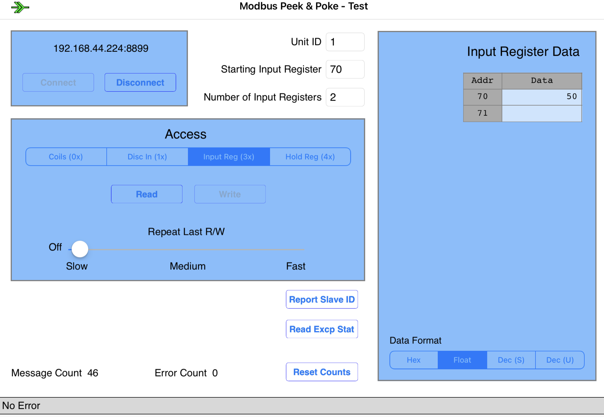
@400000006162cee823788b24 INFO Found SDM230Modbus at tcp:192.168.44.224:8899:1

@400000006162cee8303ea794 INFO registered ourselves on D-Bus as com.victronenergy.grid.cg_20153630

@400000006162cee91190e514 ERROR Unable to decode response Modbus Error: Unknown response 0

@400000006162cee915df3864 ERROR Unable to decode response Modbus Error: Unknown response 0

@400000006162cee91ad4e774 ERROR Unable to decode response Modbus Error: Unknown response 0

@400000006162cee91aebf1e4 ERROR Error reading registers 0x00-0x0d: Modbus Error: [Input/Output] Modbus Error: [Input/Output] Unable to decode request

@400000006162cee92a0462c4 ERROR Error reading registers 0x46-0x4b: Modbus Error: [Input/Output] No Response received from the remote unit

@400000006162cee938f9e63c ERROR Error reading registers 0x46-0x4b: Modbus Error: [Input/Output] No Response received from the remote unit


on the remote console (MultiPlus II-GX):

for 1 second i can see this:

1633865671110.png


and for may 5-10 seconds this:

1633865724537.png


0 Likes 0 ·
1633865671110.png (27.0 KiB)
1633865724537.png (23.5 KiB)
stanhausc avatar image stanhausc yvl commented ·

Hello @yvl.


I was having the same problem, if you delete the two identical lines of code the connection problem is solved:

Reg_f32b(0x000c + s, '/Ac/L%d/Power' %n, 1, '%.1f W'),


1637178685320.png

1637178716615.png


I believe it is due to the format:


1637178659119.png


I'll still look for more information, when I find it back here.


Good luck!

0 Likes 0 ·
1637178659119.png (30.3 KiB)
1637178685320.png (19.5 KiB)
1637178716615.png (18.3 KiB)
thomasw-1 avatar image thomasw-1 stanhausc commented ·

Hi Yvl,

the register that refer to is a holding register (designed for configuration purpose) and not an input register, where the device keeps its measurements.


See following input register definition:
1637264390662.png

Please see manual on page 2: Eastron_SDM230_Protocol v1.4.pdf

Maybe your device's firmware is not in a shape to support the KPIs yet.

0 Likes 0 ·
yvl avatar image yvl thomasw-1 commented ·
Hello,


i give up with the SDM230, after changing some Code to prevent reading more than 8 registers at once, it is working a little bit ... with mystic errors in log file and after a while it quits working.

I switched now to the SDM630 .. and this is working out of the Box ... without any errors in log file.

Thank you for tips and help, this brings me to the right direction ....

0 Likes 0 ·
yvl avatar image
yvl answered ·

Hi,

i just made a test and switch the USR-W630 with the USR-W610 connected to the SDM630. and the SDM630 appears in Remote Console without doing anything ... what crazy ...

So the USR-W610 is working as expected ....

The next thing i just tested, wars the reading with Windows "Modbus Poll" don't know what this does different, but with Modbus Poll i was only able to read up to 8 register with 1 command without an error. When i try to read 10 register, i receive an error ...

Log from Communication:

>>>>>>>>>>>>>>>>>>>>

Tx:000070-15:47:43.896-00 54 00 00 00 06 01 04 00 00 00 08

Rx:000071-15:47:43.973-00 54 00 00 00 13 01 04 10 43 65 D5 00 00 00 00 00 00 00 00 00 3C AE 1D BF

Tx:000072-15:47:44.985-00 55 00 00 00 06 01 04 00 00 00 0A

Rx:000073-15:47:45.053-00 55 00 00 00 0E 01 04 14 43 65 C1 93 00 00 00 00 00 00 00

<<<<<<<<<<<<<<<<<<<

this is corresponding to the GX log file:

Error reading registers 0x00-0x0d: Modbus Error: [Input/Output] Modbus Error: [Input/Output] Unable to decode request


But how can i change the number of registers to read at once ?

(without killing the SDM630, because this is used as grid meter, an the fast reading is needed for the ESS System)..

meanwhile i made a test with the baud rate switching from 9600 to 2400 results in reading only 6 register at once (using Modbus Poll) ...

2 |3000

Up to 8 attachments (including images) can be used with a maximum of 190.8 MiB each and 286.6 MiB total.

jurekz avatar image
jurekz answered ·

Hello Thomas

At first - thank you for yours work, it is impressive and, in fact open my eyes for that Victron Rasbperry Venus project.

Anyway, I would build DYI 3 phase power meter based on PZEM004Tv3.0 meter (or other). Of course i need somehow to connect it to Victron ModbusTCP but it should be possible with Arduino - Arduino reads that serial data and set up Modbus TCP registers which could be read by Victron Venus. I could create any register plan, but simplicity is better. I would copy register scheme from SDM630v2 and use your piece of software (maybe later when project start working it will be reneamed and published - but this is not a case now.

At first I have tried to simulate SDM630 on PC Modbus TCP simulator. And it partially work.

Victron recognize PC as SDM630, and show it in his menu.

1.jpg

2.jpg

But I could not set up any value like current or voltage.

4.jpgAnd one thing - that meter is not visible i menu? Is that correct?
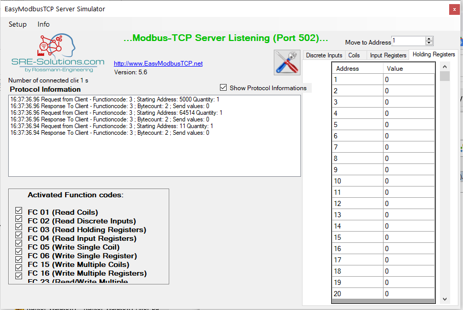
3.jpg

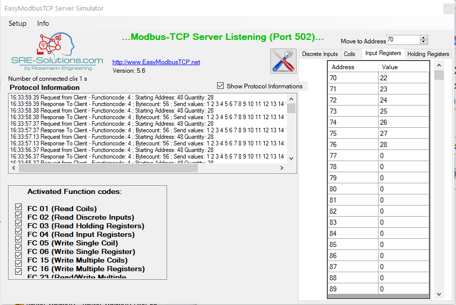
I'm not an expert in phyton but as I see we need only set up 0xFC02 (64514d) to 112dec

On the simulator i can see so Victron/that software reads from holding register:

0x000A (11dec) for 3 means 3 phases

0xFC02 (64514dec) for hardware type = 112

0x1388 (5000dec) for what? - i could not find any information what it should be there

emulator1.png

After reading hardware type start periodically reads Input Register from 0x0030 (48dec) quantity 28

emulator.png

There are summary counter - I have tried to put there some differen values, I see how it is read, but that changes are not visibly on the Victron Venus.

Any idea?

That Power Meter shpuld be visible in Energy Meters menu?

What is in holding register 0x1388 (5000dec) in real SDM630?

Could you send me table for real value from yours SDM630 for x0030 (48dec) quantity 28 - I'm going to put that value to simulator and see what is happend.

Something is missing but I do not know what.


2.jpg (26.0 KiB)
1.jpg (35.8 KiB)
4.jpg (35.6 KiB)
3.jpg (22.9 KiB)
emulator1.png (52.4 KiB)
emulator.png (63.3 KiB)
2 |3000

Up to 8 attachments (including images) can be used with a maximum of 190.8 MiB each and 286.6 MiB total.

kame avatar image
kame answered ·

Hi everybody,

@jurekz : I made some screenshots from the values I get from my sdm630 over modbus rtu:

input Register:0-99 /30001-30100

mpoll-register.jpgholding register: 0-99 /40001-40100

mpoll-holding.jpgholding register:FC00-

mpoll-holding2.jpg

So far so good.... but I also have a question and hope somebody can help me.

I have venus OS running on a raspberry a SDM630 connected to a second raspberry with iobroker. With the modbus-adapter I can read the input registers. No Problem.iobroker-read-register.jpg

Now I have a second Modbus adapter running as a Modbus TCP Slave. With NodeRed I copy the data from the RTU-side to the TCP side.Unfortunately I can not set up the holding register FC00++. So I looked for some free holding register. Instead of using FC00++ I now use the holding register 60++. I changed it in the Eastron_SDM630v2.py file.

sdm630py.jpg

sdm630py2.jpg


Victron recognize it as a sdm630 meter and I get the data:

venus1.jpg

venus2.jpg

venus3.jpg

venus4.jpg

BUT!

I have two problems:

1. the power on phase 1 is not changing. All the other values change every second (this is the time interval I read the date with the other raspberry from the meter). But the actual power/load on phase 1 changes only after a restart.

2. I set up the meter as a grid meter, but in the venus overview it is shown as a load.

venus-overview.jpg

Does somebody have an idea what I can do?

I want to use my MultiPlus as an ESS system. My SDM630 must not be shown as a "SDM630" in the display. Is there a possibility to create a simple energymeter? Maybe just one input register "total power" ore something like that.

Thank you very much.


mpoll-register.jpg (70.8 KiB)
mpoll-holding.jpg (71.9 KiB)
mpoll-holding2.jpg (86.2 KiB)
sdm630py.jpg (53.0 KiB)
sdm630py2.jpg (15.0 KiB)
venus1.jpg (37.7 KiB)
venus3.jpg (32.0 KiB)
venus4.jpg (30.7 KiB)
venus2.jpg (38.4 KiB)
venus-overview.jpg (28.5 KiB)
2 |3000

Up to 8 attachments (including images) can be used with a maximum of 190.8 MiB each and 286.6 MiB total.

yvl avatar image
yvl answered ·

Hello,

for that, may i can help:


>>>
2. I set up the meter as a grid meter, but in the venus overview it is shown as a load.
Does somebody have an idea what I can do?
<<<

You should set in Settings -> SystemSettings AC-Input1 to Grid:

1636101813869.png

regards

Yves.


1636101813869.png (64.2 KiB)
1 comment
2 |3000

Up to 8 attachments (including images) can be used with a maximum of 190.8 MiB each and 286.6 MiB total.

thomasw-1 avatar image thomasw-1 commented ·
Hi Ives,

you show the system config. Can you please show the meter config as well?


0 Likes 0 ·
jurekz avatar image
jurekz answered ·

Thank you KAME, with yours help i have started emulation of that meter. Simply my modbus emulator could not generate properly float 32 format.

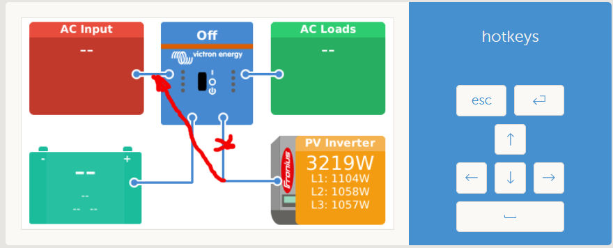
Anyway, it works - but i have similiar problem as you - metter is set as a grid metter but on Ac Input (top-left) is not any value.

I have try to set in System Setup "Ac Input 1" as a grid (as YVL wrote above) - it shpuld help - but I'm unable to do that. When I'm changing that, it changes, but after leaving that menu and come back there - ther is still set as "unknown".

What is important i do not have any Victron system - only fronius inverter and meter (Victron is planned in the future). I have found somwhere in the internet - it is imposible to set that option without victron system - but it is strange, and i unable to find that page.

2 |3000

Up to 8 attachments (including images) can be used with a maximum of 190.8 MiB each and 286.6 MiB total.

kame avatar image
kame answered ·

Hi yvl, hi jurekz,

Yvl, I tried it and I had the same problem like jurekz. When I set it to grid, the entry just diasppear when I left the menu.

The next thing I tried: I loaded a comlete new venus image to the raspberry and instead of using the sdm630 file I used the SDM230 file. As L1 amps and L1 power I used the summed values L1-L3 amps and L1-L3 power from the sdm630.

I do not know if it is because of the new image, or because of using the sdm230 file... but its working now!

Jurekz, I will try what happens to the grid meter when I disconnect my multiplus. If it is still shown an a grid meter. But probably not until wednesday.

Thanks for your help.

3 comments
2 |3000

Up to 8 attachments (including images) can be used with a maximum of 190.8 MiB each and 286.6 MiB total.

jurekz avatar image jurekz commented ·
We will wait.

Watching MQTT generated by Venus is very helpfull. As I see any dbus device generate his own topic and general topic named system is created. Some process moving the data between dedicated device topis and system topic (with some mathematic manipulation os what is needed). Quite clever :)

Unfortunetell I do not find where that connection between "AC Input 1" to "Grid" is.

But I'm going to understand that.


0 Likes 0 ·
jurekz avatar image jurekz jurekz commented ·

it looks like a key is settings in topics "system/0/Ac/ActiveIn/Source" should be "1" instead of "null". unfortunettelly it culd not be forced, is overvriten by internal process.

we have to define device vebus and set a parameter /AC/ActiveIn as in docs below

https://github.com/victronenergy/venus/wiki/dbus

But I do not have vebus device - if you have, could you check that? detailed topics and parameter.

0 Likes 0 ·
sgrigor1 avatar image sgrigor1 jurekz commented ·

Capture.PNG

capture.png

Hi,

I have a similar issues. I emulated a SDM230 meter and connected it to Venus OS. The AC load is showing the good value but I don't know how to enable AC Input.

I configured AC Input1 to Grid but when I comeback to the menu there is the same unknown state. Do you find a way to enable AC Input on dashboard?

I don't have Victorn Inverter, just a smartsolar mppt and smartshut.

Thanks

0 Likes 0 ·
capture.png (67.9 KiB)
kame avatar image
kame answered ·

morning,

with multiplus 2 connected my meter is shown as grid meter, without the mutiplus it is shown as a load.

4 comments
2 |3000

Up to 8 attachments (including images) can be used with a maximum of 190.8 MiB each and 286.6 MiB total.

jurekz avatar image jurekz commented ·

Have you set something in "Settings/System setup/AC input" ?

Without multiplus is unable to set it up, is still "undefined". Maybe Multiplus set that as a grid?

Could you enable MQTT on Venus (both MQTT and MQTT plain) connect MQTT Explorer and look where is the differences? (If venus do not write properly MQTT topics you have to modyfy /service/dbus-mqtt/run and add the --keep-alive 0 option at the end

Like that:

exec softlimit -d 100000000 -s 1000000 -a 100000000 /opt/victronenergy/dbus-mqtt/dbus_mqtt.py --init-broker --keep-alive 0

If you have that - you shpuld see vbus or inverter topics(dbus device) could you expand all topics and make printscrin for that? I need that to different project.


0 Likes 0 ·
jurekz avatar image jurekz jurekz commented ·

I have make some scrinschot and how it look like:

Only fronius inverters - inverters conection are set to "Ac Input" - however Venus showing it as connected to "somewhere else":

no-meter-venus.jpg

VRM shows that inverter as connected to the "Output" what is not what is set in configuration

no-meter2-vrm.jpg

Let's look into MQTT

no-meter3-mqtt.jpg

We can see so that virtual DBUS module called system - assume that all power is exported to the Grid. However it is not shown on Venus and VRM. I think this is still the same issue - system settings AC input have to be set to grid - maybe this is that MQTTtopics AC/ActiveIn/Source?

Anyway - let's connect meter: Import 90W

meter-venus.jpg

As we can see that 90W is added to loads. Quite smart - if grid meter showing 90W import - consumption is all we produce on PV and that import - right! But no value on Ac Input is showing.

image5-vrm.jpg

More or less similar on VRM

Le's look into MQTT

image8-mqtt.jpg

We can see the grid value properly rewritten from the meter, and calculated consumption.

I thin all of that is because we are unable to set up that parametr

image7-venus-settings.jpgwithout venus device

image10-mqtt2.jpg

We need something like DBUS dummy device simulated the Vebus device - and all should work. Could someone check how that values looks like with Victron module connected and disconnected?

0 Likes 0 ·
no-meter-venus.jpg (47.9 KiB)
no-meter2-vrm.jpg (31.6 KiB)
no-meter3-mqtt.jpg (120.8 KiB)
meter-venus.jpg (54.8 KiB)
image5-vrm.jpg (34.7 KiB)
image8-mqtt.jpg (124.7 KiB)
image10-mqtt2.jpg (71.1 KiB)
thomasw-1 avatar image thomasw-1 commented ·
Kame,

in die meter setup you can define the function that the meter shall cover.
Did you check that?

0 Likes 0 ·
jurekz avatar image jurekz thomasw-1 commented ·
role on meter is set to grid - but it not helps until we do not set in system settings AC1 to grid as well - but it does not work until you do not have central Victron device.
0 Likes 0 ·
jurekz avatar image
jurekz answered ·

I have instaled test version 2.80 and there is something changed

1) Venus shows proper AC Input!

image1.jpg

2) VRM not :)

image2.jpg3) System Settings AC input still unable to set up to Grid

4) Changes in MQTT - many data is lost now

I'm goint to test that a little bit deeper and comment in the 2.80 thread and ask developers why that working in that way.


image1.jpg (51.2 KiB)
image2.jpg (30.8 KiB)
3 comments
2 |3000

Up to 8 attachments (including images) can be used with a maximum of 190.8 MiB each and 286.6 MiB total.

jurekz avatar image jurekz commented ·

Have anyone connect SD630 direct to the Venus (Rasbppery) via RS485/USB converter?

Looking into code it shpuld work (however I'm not an expert).

Or maybe this is a problem that particular developers version?

0 Likes 0 ·
jurekz avatar image jurekz jurekz commented ·

OK, I have found so it has to be TCP. Anyway, with cheapest chinese converter Elfin-EW11 working pretty well.


0 Likes 0 ·
sgrigor1 avatar image sgrigor1 commented ·
Did you figured out how to show AC Input power on VRM dashboard? I have the same issue.
0 Likes 0 ·
jurekz avatar image
jurekz answered ·

Hello

I have problem with reading current from phases. What is strange other data are loaded correctly. Probem is only with current on phases and summary current. I have checked in the code and it looks correct.

I have read that by node-red and GridMeter works correct.

Another issue is reading Frequency - it should be read with one place after dot precision but it wasn't it always read as 49.0 however counter show it correctly and could be read by node-red correctly.

Maybe this is a problem with newest version of Venus - I have installed v2.80-36

3 comments
2 |3000

Up to 8 attachments (including images) can be used with a maximum of 190.8 MiB each and 286.6 MiB total.

thomasw-1 avatar image thomasw-1 commented ·
Hi Jurek,

Since variables are handled differently in python 3.x, I would not exclude the possibility that this leads to your described constraints. Currently I use an ABB meter and not the Eastron anymore. Therefore my test capabilities are a bit limited.
At least for the ABB meter frequency and current are properly transferred with latest beta GX firmware.

During next few days I will publish a new generic package that include 2 more meters, which includes in the code for the Eastron additionally a scale-defintion that could properly solve your issue with python 3.


0 Likes 0 ·
jurekz avatar image jurekz thomasw-1 commented ·

If you would test that before publishing - email me - currently i have test instalation so this is not a problem for me.

0 Likes 0 ·
thomasw-1 avatar image thomasw-1 jurekz commented ·
Hi Jurek,

I sent you a version that you can try on the current GX release.
You can delete your email address from your previous post.


0 Likes 0 ·