question

escaping-swedes avatar image
escaping-swedes asked

need help checking my installation.

Hi Guys, I’m new here to this community but I have read through some of the questions and answers and it seems like you guys know what you are talking about.

So, I thought I might share my story here and se if someone more knowledgably then me can have a look at my installation.

I´m in the process of preparing my Holyday Rambler (RV) for full time living with my family (Wife and two kids). After looking at Motorhomes here in Sweden we realised none of the existing motorhomes in our prize class hade the technical set up we wanted so we decided on a older American RV and then fixing it up and installing lithium battery with a new inverter and all that comes with it. And I Found a good dealer here in Sweden, so I ended up going all in Victron.

So That’s the story behind this noob asking questions.

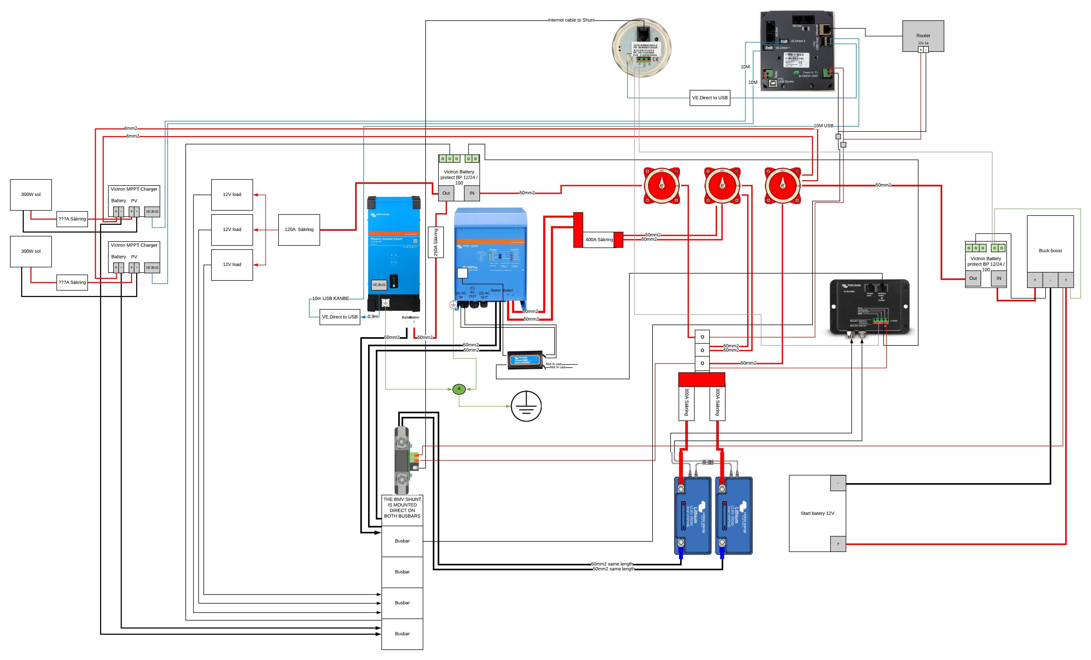
I have used the Victron Volkswagen and some other drawings as referents when I did all the wiring. So now I only have some smaller installation work left before I need to configure this whole system but before hooking any power to this system, I’m hoping someone can give me and second opinions on my wiring diagram.
Thanks // Henrik

installationdesign
rv.jpeg (468.9 KiB)
2 |3000

Up to 8 attachments (including images) can be used with a maximum of 190.8 MiB each and 286.6 MiB total.

4 Answers
klim8skeptic avatar image
klim8skeptic answered ·

Hi Henrik,

A few things need attention,

Mppt, no fusing? and undersized cabling. Always install appropriate fusing, and use the thickest and short cable that will fit the mppt terminal.

BP 12/24/100 used on the pheonix inverter. The Pheonix will draw 200a driving a 2000w load. I don't think that any BP would be appropriate for such a large inverter.

BMV shunt (as pictured) wired up backwards.

Batteries are under capacity, compared to the available loads. The recommended discharge per battery is 100a.

A 2000w inverter and a 3000w inverter/charger seems overkill.

1 comment
2 |3000

Up to 8 attachments (including images) can be used with a maximum of 190.8 MiB each and 286.6 MiB total.

On @klim8skeptic's point of the battery protect, please read the manual for that product regarding how to use it with an inverter.

It should be wired as a signal to the remote on/off port, NOT used to isolate the positive DC supply.

0 Likes 0 ·
Guy Stewart (Victron Community Manager) avatar image
Guy Stewart (Victron Community Manager) answered ·

Hi @Escaping Swedes,

Looking at other people's wiring diagrams is a bit like a Where's Wally.

One thing I noticed was the VE.bus connection between the MultiPlus and the CCGX is missing.

2 |3000

Up to 8 attachments (including images) can be used with a maximum of 190.8 MiB each and 286.6 MiB total.

escaping-swedes avatar image
escaping-swedes answered ·

Thanks for the reply.

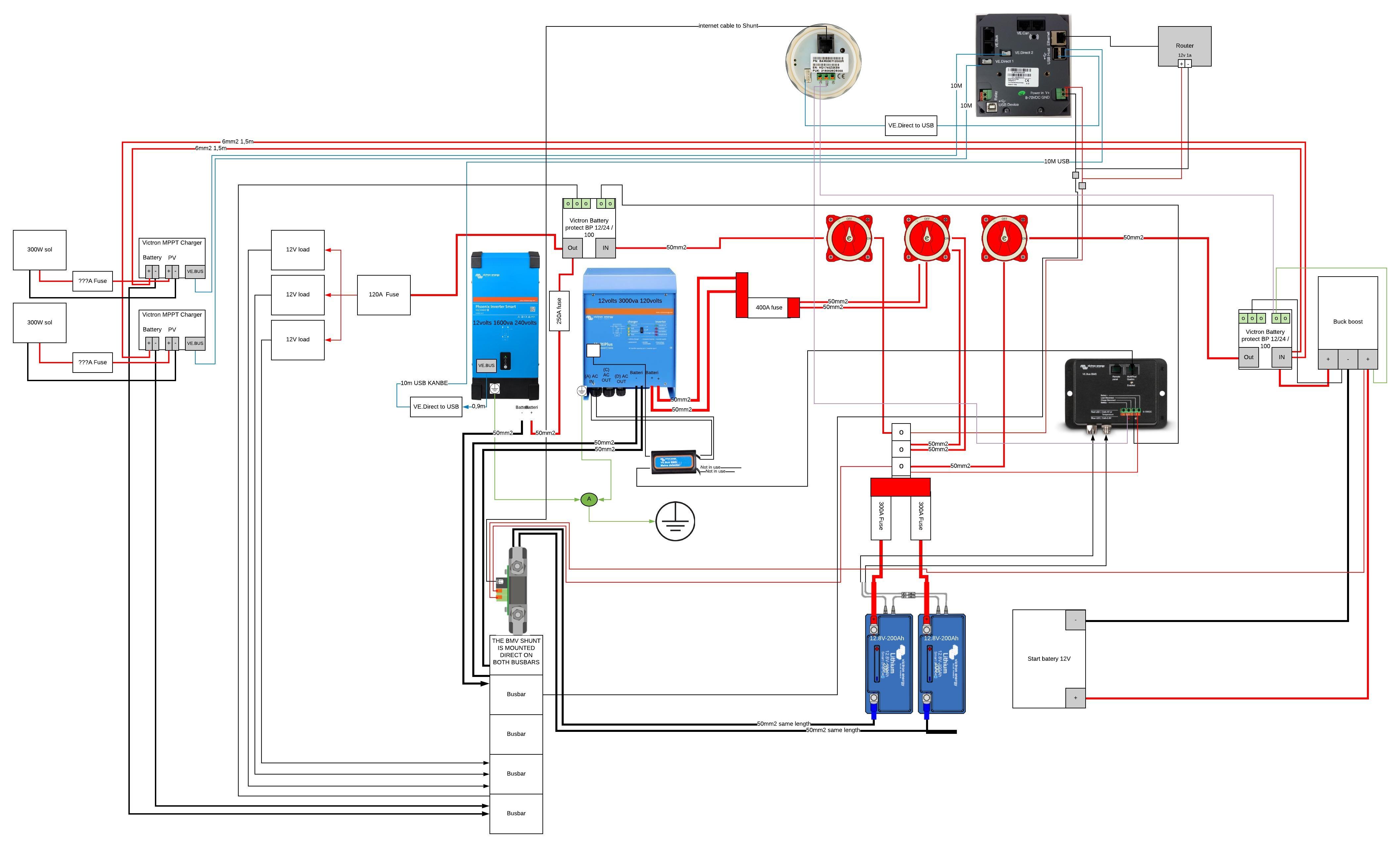
With the MPPT made a mistake in the drawing. PV out goes through the battery protect 12/24/100 before going back to the batteries.

The cable is about 1,5m long from the MPPT to the Battery protect. Here I used 6mm2 but I can see if I can fit any thicker cable in to the terminals. For fusing should I have a fuse between the MPPT and the battery protect? And can you help sizing that fuse? I installed a fuse between the Solar panels and the MPPT that I also thought could dubbled as a off switch when doing work on the system. But don’t really know how to size it. I use 6m of 6mm2 cable fore 300watts of panels.


For the Phoenix inverter I used the wrong picture, the one I have is 1600VA with is the smallest smart Phoenix inverter I could get (thought of getting a smaller but I wanted to be able to turn it on and off from the ccgx control inside).

To my understanding the 1600va Phoenix inverter draws roughly 1300 watts and the 3000va multiplus draws 2400 watts?

The reason I went with this setup is that the RV is running on 120volts with is the Multiplus and the Phoenix inverter is supposed to power a few outlets so that I can get 240 volts.

And I see I used the wrong image on the battery as well I have the 200ah battery’s

And the 200Ah smart batteries have 200A Recommended continuous discharge current.

And the Shunt is mounted correct, another drawing mistake.

Thanks


rv-rev2.jpeg (486.5 KiB)
2 comments
2 |3000

Up to 8 attachments (including images) can be used with a maximum of 190.8 MiB each and 286.6 MiB total.

Matthias Lange - DE avatar image Matthias Lange - DE ♦ commented ·

Instead of using a BP to switch on/off the MPPTs/BuckBoost you can use the "charge disconnect" signal directly.
Also the Phoenix can be switched directly with the "load disconnect".
All that devices have a remote port for that.

The power for the CCGX, the Router and the BMV must come from behind the load BP (or the "load disconnect" terminal).
The only device connected directly to the batteries is the VE.Bus BMS.

The negative of the BuckBoost has to be connected to you neg busbar.

0 Likes 0 ·
Show more comments
escaping-swedes avatar image
escaping-swedes answered ·

Hi Guy Stewart,

Yes I haven’t drawn that in yet.

When I did the wiring in my RV I actually run two networkable from the CCGX. One to the multiplus and another to the BMS remote panel port, but not sure with one to use?

1 comment
2 |3000

Up to 8 attachments (including images) can be used with a maximum of 190.8 MiB each and 286.6 MiB total.

Matthias Lange - DE avatar image Matthias Lange - DE ♦ commented ·

If you want to control the Multi remotely you need a "Digital Multi Control".
With a VE.Bus BMS installed you can't use the CCGX as remote.

0 Likes 0 ·

Related Resources

Additional resources still need to be added for this topic