question

vicky avatar image
vicky asked

How to add PV meter on AC out1 (Multigrid / Venus)

Hi, still progressing with my setup. Was fun to have the first sun today charging the batteries :).


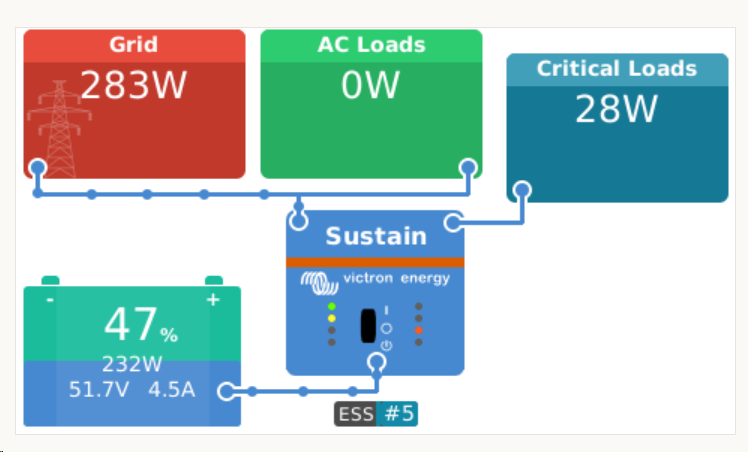
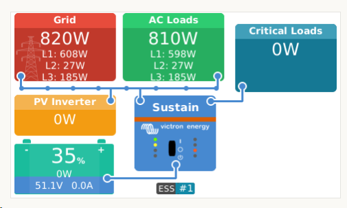
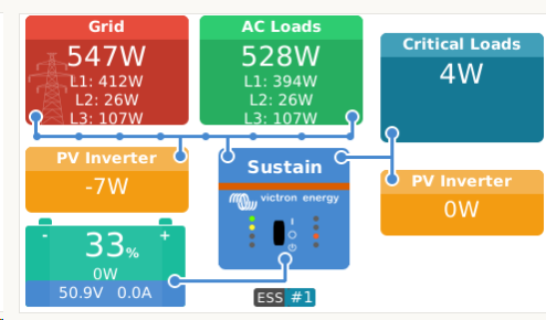
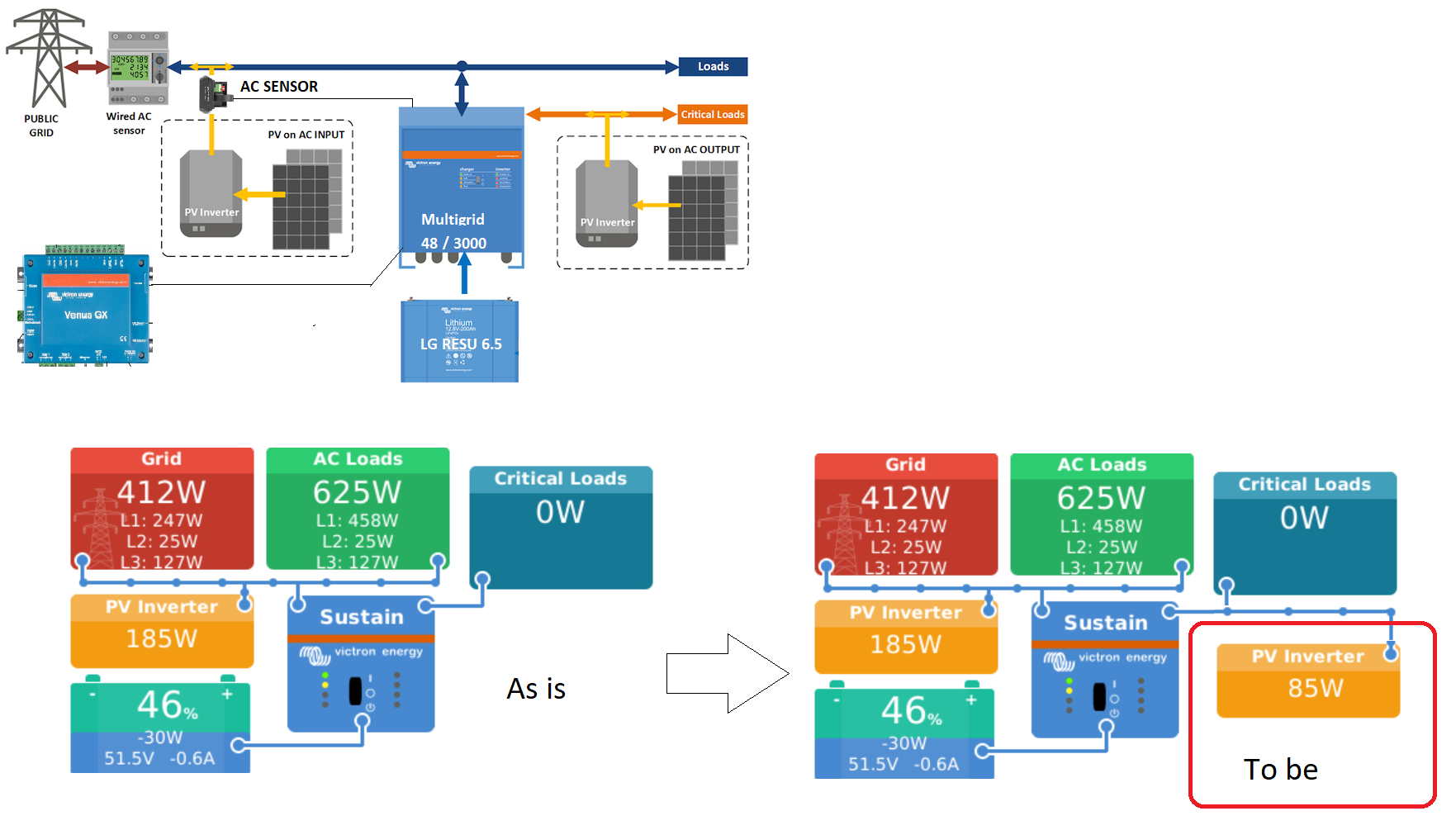
Picture shows my current setup and the current remote console below.
Reading critical loads "0W" is OK as there is no load currently, however the PV inverter on AC Out1 is delivering AC power. However I am missing the meter for the PV inverter on ACout1 in the remote console. I'd like to have as the "to be".

What did I lack to do ?

Txs

Energy Meter
1545744189948.png (382.2 KiB)
2 |3000

Up to 8 attachments (including images) can be used with a maximum of 190.8 MiB each and 286.6 MiB total.

17 Answers
mvader (Victron Energy) avatar image
mvader (Victron Energy) answered ·

Hi Vicky; you do have both meters for the PV Inverters installed; right?


In Settings -> meters, check their location or position. You have to tell the system where those meters / PV Inverters are wired into the system.

2 |3000

Up to 8 attachments (including images) can be used with a maximum of 190.8 MiB each and 286.6 MiB total.

vicky avatar image
vicky answered ·

Hi mvader, actually I have the Et340 grid meter and the AC Sensor set up (using an assistant) both work. I was assuming the AC1 out has it's own internal meter as it can measure Loads on AC1 out.... Did I miss a point here, do I need another external meter?

2 |3000

Up to 8 attachments (including images) can be used with a maximum of 190.8 MiB each and 286.6 MiB total.

mvader (Victron Energy) avatar image
mvader (Victron Energy) answered ·

Ah; yes; you do: on ac out there can be both loads and pv inverters. To visualize the PV Inverter on AC Out; you need an extra meter.


See also here:

https://www.victronenergy.com/live/ccgx:start#measuring_pv_inverter_output

2 |3000

Up to 8 attachments (including images) can be used with a maximum of 190.8 MiB each and 286.6 MiB total.

vicky avatar image
vicky answered ·

I see, understood.
Thanks, so I'll go for an ET112 as the AC Sensor's accuracy is a bit poor.

1 comment
2 |3000

Up to 8 attachments (including images) can be used with a maximum of 190.8 MiB each and 286.6 MiB total.

mvader (Victron Energy) avatar image mvader (Victron Energy) ♦♦ commented ·

Yes; sorry for this. By the way there is a Small chance its not needed: what type PV Inverter do you have? You could check if it supports ModbusTCP (requires a wifi or LAN port on the pv inverter)

0 Likes 0 ·
vicky avatar image
vicky answered ·

No worries, txs for the hint. My PV inverter (EVERSOL TL-3000) has a RS485 interface, no IP based one. However I didn't find any detailed information about the interface or protocol. Originally it was supposed to connect to the ZEVERSOL Cloud in China through a gateway. Definitely not where I will connect into. I'd rather stay in Europe ;o), and buy another meter.

2 |3000

Up to 8 attachments (including images) can be used with a maximum of 190.8 MiB each and 286.6 MiB total.

vicky avatar image
vicky answered ·

Still stuck with the meters... I removed the AC Sensor and it's assisitant. Then added the first ET112 instead to the bus. Configured it, but doesnt't work. As soon as both meters are connected it is screwed up. None of the meters works. See attached PDF


1 comment
2 |3000

Up to 8 attachments (including images) can be used with a maximum of 190.8 MiB each and 286.6 MiB total.

wkirby avatar image wkirby ♦♦ commented ·

Where are the meters installed? More specifically, are they both on the same end of the RS485 - LAN converter that you have or is one of the meters going through the LAN and the other one direct RS485. Just trying to understand terminations etc.
It seems like you have assigned the ET112 meter a different ID to the ET340 right?

0 Likes 0 ·
vicky avatar image
vicky answered ·

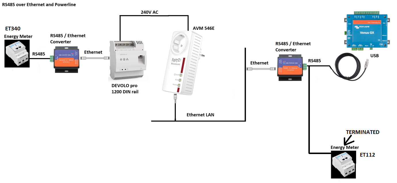
Txs for asking, here is how it looks like. And Yes, there are differend IDs for the meters

Cable length from Venus to converter is as delivered, from converter to ET112 is 1.5 meters.
I wasn't able to figure out internal schematics of the converter yet, have asked the support if there is a termination inside


1546246821877.png (271.5 KiB)
1 comment
2 |3000

Up to 8 attachments (including images) can be used with a maximum of 190.8 MiB each and 286.6 MiB total.

wkirby avatar image wkirby ♦♦ commented ·

Those cable lengths should be short enough without terminators.

What mode are you running the "304's" in? I'm wondering if the ET340 cannot "hear" the ET112 and it assumes that it can just transmit, therefore the ET112 never gets a chance to transmit on the bus.
Maybe the ET112 does try and transmit, but the ET340 does not know that there is data on the bus and transmits over the top of the ET112 and the ET340 doesn't even realize it has caused a collision on the ET112 end.

As a test, what would happen if you wired the ET112 up at the same end as the ET340?

0 Likes 0 ·
vicky avatar image
vicky answered ·

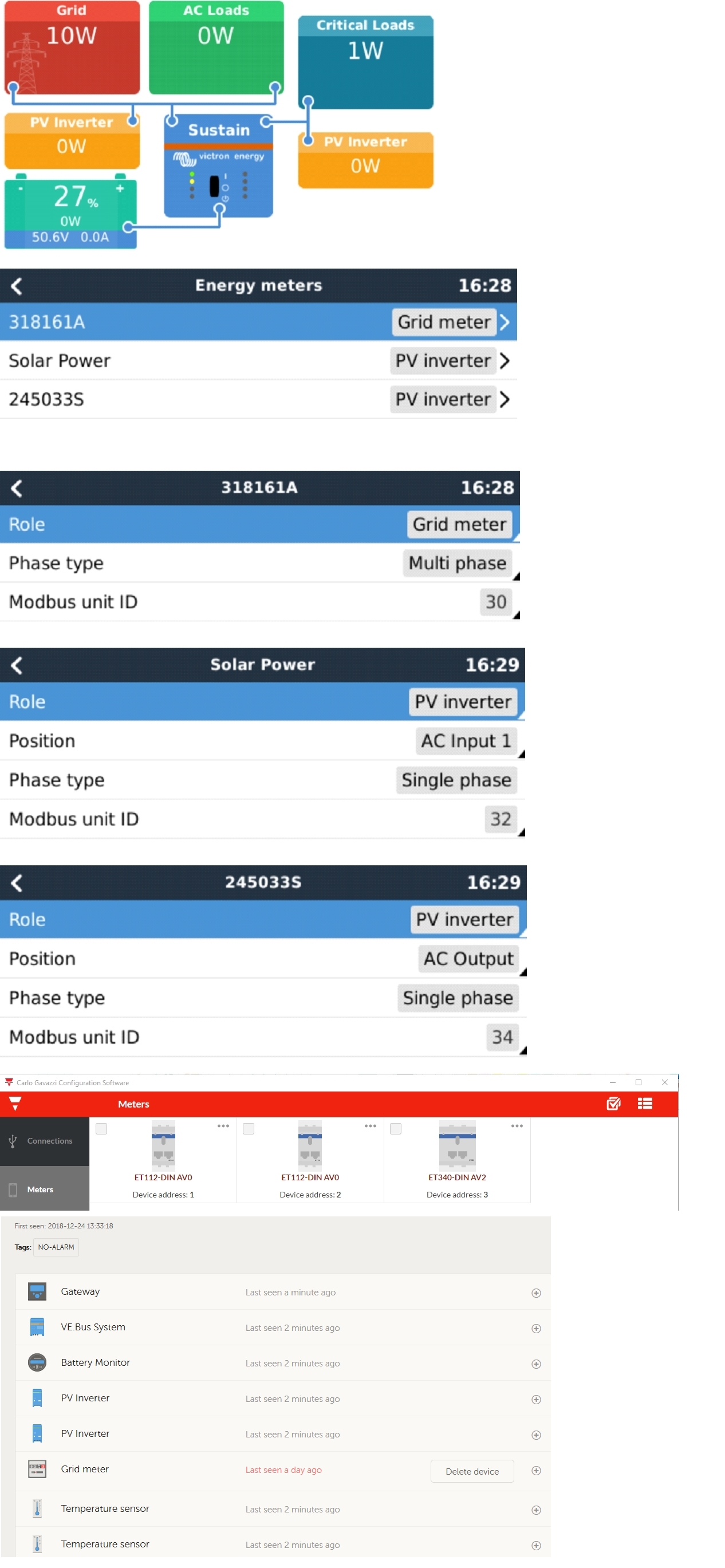
The 304's are running in TCP Server mode (connected to ET340) and TCP Client mode (connected to Venus). For the test I connected the ET112 to the ET340 end. Both meters' red LEDs are indicating active communication, but this is how it looks like now :o(
For another test I switched the 304s mode, server to client and client to server - no change either.


1546269442727.png (75.8 KiB)
7 comments
2 |3000

Up to 8 attachments (including images) can be used with a maximum of 190.8 MiB each and 286.6 MiB total.

wkirby avatar image wkirby ♦♦ commented ·

Both meters should have worked on that side without any changes to the configuration of the 304's.
Now I'd want to perform a sanity check and exclude the 304's completely and get both meters going working with the Venus on a native RS485 network, then work back from there.
I can only imagine that moving the ET340 will be a nightmare for you. Would it be possible to run a temporary RS485 cable in to test? However, you will almost certainly need to set the terminators if your cable is longer than a few metres.

0 Likes 0 ·
vicky avatar image vicky wkirby ♦♦ commented ·

For testing I did run the cable three storeys down, through the stairway into the basement, so my 304s are completely removed now.
I terminated at the last meter (ET112). However, same behaviour. :(
So the 304s are Not the problem.
For a quick check I did disconnect the ET340 to check if ET112 will work if being the only device , and after a Venus reboot it worked. However, even after a reboot the ET340 the 3phase Grid meter, is still shown under Settings/energy meters although it is disconnected from RS485 and doesn't show any communication.


0 Likes 0 ·
1546357554624.png (68.1 KiB)
1546358556358.png (29.7 KiB)
wkirby avatar image wkirby ♦♦ vicky commented ·

Did you terminate at the USB converter end too? There is a 120Ω resistor on brown and green wires.

https://www.ftdichip.com/Support/Documents/DataSheets/Cables/DS_USB_RS485_CABLES.pdf


0 Likes 0 ·
vicky avatar image vicky wkirby ♦♦ commented ·

tried with and w/o this termination, no difference :o(

0 Likes 0 ·
vicky avatar image vicky wkirby ♦♦ commented ·

is there any chance to debug the RS485 data ?

0 Likes 0 ·
Show more comments
vicky avatar image
vicky answered ·

@WKirby Didn't receive my second meter yet to do further testing. However I am struggling with what I just read in the ET112 manual. Didn't see this yet.


"To connect multiple Energy Meters, wire each meter to a separate RS485-USB converter. Which are then each plugged into a separate USB socket on the CCGX. See NOTE 1 Below
Connecting multiple ET112 meters to the same RS485-USB cable is not possible: the ET112 meter has no display and its Modbus address can therefor not be changed.
Note 1 You can connect the ET112 in parallel, just need to change the MOD address to another
number using the Configuration software from the supplier which is free from Carlo Gavazzi Web site"

Can I connect them in parallel now or do I need a second USB- RS485 converter ?? The Modbus ID is already different...Or is the modbus something different than MOD address?
I can't fin the right software at CG website btw, maybe somebody coudl drop me a link?


If I need a second USB-RS485, how will it work with three meters then ?

At the end my setup shall look like
ET340 - 3 phase Grid meter
1st ET112- Meter to capture PV input of PV inverter #1
2nd ET112- Meter to capture PV input of PV inverter #2

Sorry for bugging you folks, I still seem to have a steep learning curve :o))


2 |3000

Up to 8 attachments (including images) can be used with a maximum of 190.8 MiB each and 286.6 MiB total.

wkirby avatar image
wkirby answered ·

It's only saying that you need a separate RS485-USB because it is difficult to do without a display on the device. It can be done with the software.

BUT, for now we have differnt MODBUS ID's / address, it is the same thing. So the MODBUS address does not seem to be the problem right now. It will be a problem with another ET112, but we can sort that out another time. I am assuming that you didn't change the MODBUS ID from new because you didn't have the software and I aslo think that the ET340 and ET112 have different addresses from new anyway.

Software, Carlo Gavazzi website is awful!!

Go here: http://www.gavazziautomation.com/ then under the map search "ET112" then click the PDF file near the bottom where it says ET112, then a window comes up with PDF and ZIP!

3 comments
2 |3000

Up to 8 attachments (including images) can be used with a maximum of 190.8 MiB each and 286.6 MiB total.

vicky avatar image vicky commented ·

Ok, got it. You are right IDs havent been changed, they were and different.
Downloaded the files txs for the link. Now I'll wait for the nex ET112 and get back here as soon as I know more after testing.

0 Likes 0 ·
Rob Duthie avatar image Rob Duthie vicky commented ·

Hi

I have a copy of the software if required for the Carlo meters for programming and changing the Mod bus ID , as i running a similar system with meters in parallel and a PV inverter on the input and on one the output, on one USB lead back to the Raspi unit CCGX display controller.

The Carlo software displays all the paraemeters and graphs like the CCGX unit does if required , very easy to use and setup. etc.

email me if required raduthie@gmail.com

0 Likes 0 ·
vicky avatar image vicky Rob Duthie commented ·

Thanks, this sounds promising ! I will for sure e-mail you if I get stuck :o)

0 Likes 0 ·
mvader (Victron Energy) avatar image
mvader (Victron Energy) answered ·

Hi; just a very short comment (I havent read all thats been said already, sorry, and could be that you’re already past this; but still wanted to share it)


1) if all the meters show up in de device list; and show voltage, then there is no need to worry about rs485 conmunication or IDs. The digital communication then works. If they don’t all show up: you now know where to look: rs 485 wiring and IDs.

Once they do show up:

2) check, in the device list; that for each, the voltage, current and power are all correct. If they are not, check your AC wiring. Everything shown here in the device list comes straight from the meters: I cant think of any ccgx/venus settings that could be wrong causing issues here.

Once thats all fine:

3) go to overview, and check that. If wrong; check your settings wrt to the positions/locations of each meter: pv inverter on ac out, vs on ac in. This needs to be correct for the system to do the calculations properly.


All done.


Hope that helps!

2 |3000

Up to 8 attachments (including images) can be used with a maximum of 190.8 MiB each and 286.6 MiB total.

wkirby avatar image
wkirby answered ·

I have had another quick read through from the top including the PDF.
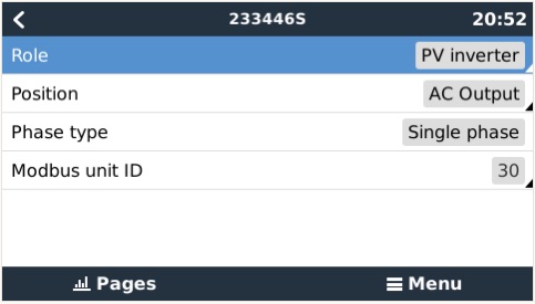
Matthijs has repeated a point in step 3, which he did mention earlier on in the thread. I thought you had done it, but looking through again, I can't see it. That is the "Position" of the PV-Meter as in the system location of the PV Meter ET112. Did you move it in the system to AC-OUT like this:


pv-meter.jpg (30.7 KiB)
2 |3000

Up to 8 attachments (including images) can be used with a maximum of 190.8 MiB each and 286.6 MiB total.

vicky avatar image
vicky answered ·

getting frustrated with these meters....
Received the third meter today, so I did some testings. Connected each meter to the PC and used CG config software. Total cable lenght at max 5 meters.
All meters showed the same device ID (1). So I changed them to 1,2,3.
The firmware is different on all meters B2 / B3 / B4 !?

Then plugged the USB into the Venus and did power off/on there.
All meters are shown under settings / energy meters. Modbus Unit ID 30/32/34
ET340 3Phase grid meter, first ET112 as PV inverter AC in, second ET112 PV inverter AC out. However only grid meter and one of the ET112 was shown on graphics of the Rconsole and VRM portal

Next I changed the meters device ID using CG software to 1,2,3, where this time I did rearrange it equivalent to the device's location on the bus. I.e. device closest to Venus receives ID1, next is ID2, farthest away ID3.
Restart and....both ET112 shown in Rconsole and VRM, however ET340 gone now :o(. So this definitely changed something, but didn't fix it. Still two meters only.

Finally, big mistake obviously, I did change the device IDs of the ET meters to 30/32/34 which worked, settings have benn written and I was able to check with th CG software once, but since then I can no longer access any of the meters, not even if locally and individually wired to either venus or PC.

The more I try to get this running the more questions I get and the more I am really frustrated.
I.e. why does the Venus keep all meters in its settings screens, even when none is connected?
When I had the ET340 only, it was still in settings, even when not connected. When I added and removed the first ET112, same, adding removing second ET112 same. SO I still have three meters in Venus, but none connected :o(
Are here maybe related settings which are initially stored and not changed correctly when meters are changed?
Can the different Meters Firmawre maybe the issue ? Where to get / Update the firmware?

I really do like the ESS idea and system, but this meter issue drives me nuts

2 |3000

Up to 8 attachments (including images) can be used with a maximum of 190.8 MiB each and 286.6 MiB total.

wkirby avatar image
wkirby answered ·

"All meters are shown under settings / energy meters. Modbus Unit ID 30/32/34
ET340 3Phase grid meter, first ET112 as PV inverter AC in, second ET112 PV inverter AC out. However only grid meter and one of the ET112 was shown on graphics of the Rconsole and VRM portal"

At this point you were in the right place, you had all meters there in the list. Did you set the Role AND Position for each one at this point?
For ET340, Role should be Grid, then three phase (or single phase).
For ET112 on AC-IN , Role should be PV inverter, Position should be AC Input 1 (or 2 if Quattro).
For ET112 on AC-OUT, Role should be PV inverter, Position should be AC Output

This way the system knows what each meter does and where you will be wiring it in. If you have set the phase type as "three phase" for the ET340, then you should see three phases in the red "Grid" tile. Then each of the ET112 meters will create a yellow tile called PV Inverter on each side of the MultiPlus tile. If two of the meters have the same position, then you will only see one of them. I can imagine the frustration, but please persevere! It will be so cool when it's running!

1 comment
2 |3000

Up to 8 attachments (including images) can be used with a maximum of 190.8 MiB each and 286.6 MiB total.

vicky avatar image vicky commented ·

Yes I had set each role AND position but as I stated, only two yellow PV inverter meters have been shown in the graphics, the 3Ph grid meter was gone.
I am quite sure I have a reset problem here as the three meters are still shown in settings w/o being even connected.

0 Likes 0 ·
vicky avatar image
vicky answered ·

@mvader

Hi gents,

I am back in business ;o)
Having had my energy meters "playing dead", I connected one, started the CG config software and initiated the "connect". Progress started with 1% super slowly. So I waited for almost 2 hours until 100% was reached AND THE METER WAS DETECTED :). I set the device ID back to "1" and 2/3 for the other two meters.

They all connect like a charm to the CG software within seconds now. No matter if I go direct wire or through my freaky Converter, Ethernet, Powerline setup.

However.....only two of my three meters show up in the graphics.
So I am afraid I have to leave this issue with the Victron staff as the RS485 definitely works well.


3 comments
2 |3000

Up to 8 attachments (including images) can be used with a maximum of 190.8 MiB each and 286.6 MiB total.

vicky avatar image vicky commented ·

getting closer.... if ET340 must be set as device ID1 with CG software, else it doesn't show up as a 3Ph Grid meter. Tried ID5 then it shows up as 1Ph Meter :o(.
The second meter has to have ID2 then it shows up as well, either AC Out or AC IN
Didn't figure out yet what the third meter expects to be.... ID3 doesn't work - simply doesn't show up.

0 Likes 0 ·
vicky avatar image vicky vicky commented ·

No sun @ 7:30 pm ;o) and no critical loads, so readings are OK

0 Likes 0 ·
1547231734438.png (49.7 KiB)
vicky avatar image vicky vicky commented ·

If you want to SSH into the Venus I can grant you access of course

0 Likes 0 ·
vicky avatar image
vicky answered ·

After a sleepless night, thinking about the issue, I made it :o)
I had an old USB/RS486 adapter sitting in my shop since years. So I gave it a try and connected it to the third meter, to which I addigned ID1. Venus reboot - here you go.

I am far from being pleased by the efforts I had to invest to get three simple meters up and running, but for me it is working now. Hopefully Victron will look into this and fix it for the future.

Now looking to the next sunny day to see if load and PV power / yield calculations are OK.

have a sunny day


1547275696742.png (52.7 KiB)
1547275992024.png (52.2 KiB)
2 |3000

Up to 8 attachments (including images) can be used with a maximum of 190.8 MiB each and 286.6 MiB total.

wkirby avatar image
wkirby answered ·

YAY! The battle is won.
It is interesting though why no more than two meters would work on the same bus. I only have two meters, so I cannot test this, but it is strange.

Thank you for sharing everything, I especially like the setup with the 304 converters, I might need something like that one day.

1 comment
2 |3000

Up to 8 attachments (including images) can be used with a maximum of 190.8 MiB each and 286.6 MiB total.

vicky avatar image vicky commented ·

Oh man, I am happy to...

Quick Link to the "304 converters"

0 Likes 0 ·

Related Resources

Additional resources still need to be added for this topic

Energy Meter Selection Guide