question

alaskannoob avatar image
alaskannoob asked

What controls charge going into batteries in DVCC?

I have 8 x Pylontech US5000 in my Victron system set up with DVCC and my MPPT is a SmartSolar 450/200. I was under the impression that the batteries told the MPPT how much charge they wanted. But I've noticed that when the batteries charge up to about 90%, the current going into them gets severely limited despite a) there being plenty of PV available and b) the CCL set by the batteries is much higher.

Just now I recorded the batteries throttled at 90% where only about 7 amps was going into them at 90% SOC, and the MPPT was showing only 707W coming in. So I turned on a space heater to confirm, and instantly the MPPT ramped up to 2000W to cover the load.

So does the MPPT lower the charge current independently of what the batteries are asking for? That seems to be the case.

DVCC
2 |3000

Up to 8 attachments (including images) can be used with a maximum of 190.8 MiB each and 286.6 MiB total.

4 Answers
mondeoman avatar image
mondeoman answered ·

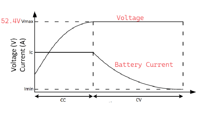
52.4 V is the maximum voltage that Pylontech batteries are charged to in Victron systems. And that is just fine, even if the batteries are requesting 53.2V.

Up to 52.4V, the charger works in constant current mode. It just pushes amps into the battery up to a maximum limit (the lowest between battery requested CCL, DVCC charge current limit entered by the user or the max. charge current configured in the MPPT charger or the illumination on the panels).

When the voltage reaches 52.4V, the charger enters the constant voltage phase. It maintains this constant voltage at its output and that obviously means fewer and fewer amps can be pushed into the battery. In the "constant voltage" phase, it may appear that the current is throttled by the charger.

This is the "CC/CV" charging algorithm that is standard procedure for charging Lithium batteries.

Now if you put an additional load, the voltage has a tendency to drop below 52.4V and the charger begins to push amps to raise and hold the voltage to 52.4 V.

PS: You can't tell anything about the cell balance at cell voltages below approximately 3.45V. You could have an imbalance of 10% state of charge and the cells would have very, very close voltages.

cc-cv.png


cc-cv.png (31.1 KiB)
4 comments
2 |3000

Up to 8 attachments (including images) can be used with a maximum of 190.8 MiB each and 286.6 MiB total.

nickdb avatar image nickdb ♦♦ commented ·
You are right. I keep forgetting this pylon quirk.

So SOC is inaccurate.

0 Likes 0 ·
alaskannoob avatar image alaskannoob commented ·

In my video you see the battery voltage is 52.32 which would mean it falls under the constant current model in your explanation.


Which you state means it pushes amps into the battery up to the lowest of:

a) CCL (which is 160A in this case)

b) DVCC charge current limit entered by the user

c) or the max. charge current configured in the MPPT charger or the illumination on the panels

Without going in and checking any settings for b) and c) above, I assume those are good given that my battery routinely charges with the MPPT pushing 140-150 amps into it. If b) or c) above was the issue, I would never see that kind of current from the MPPT going into the batteries, correct?

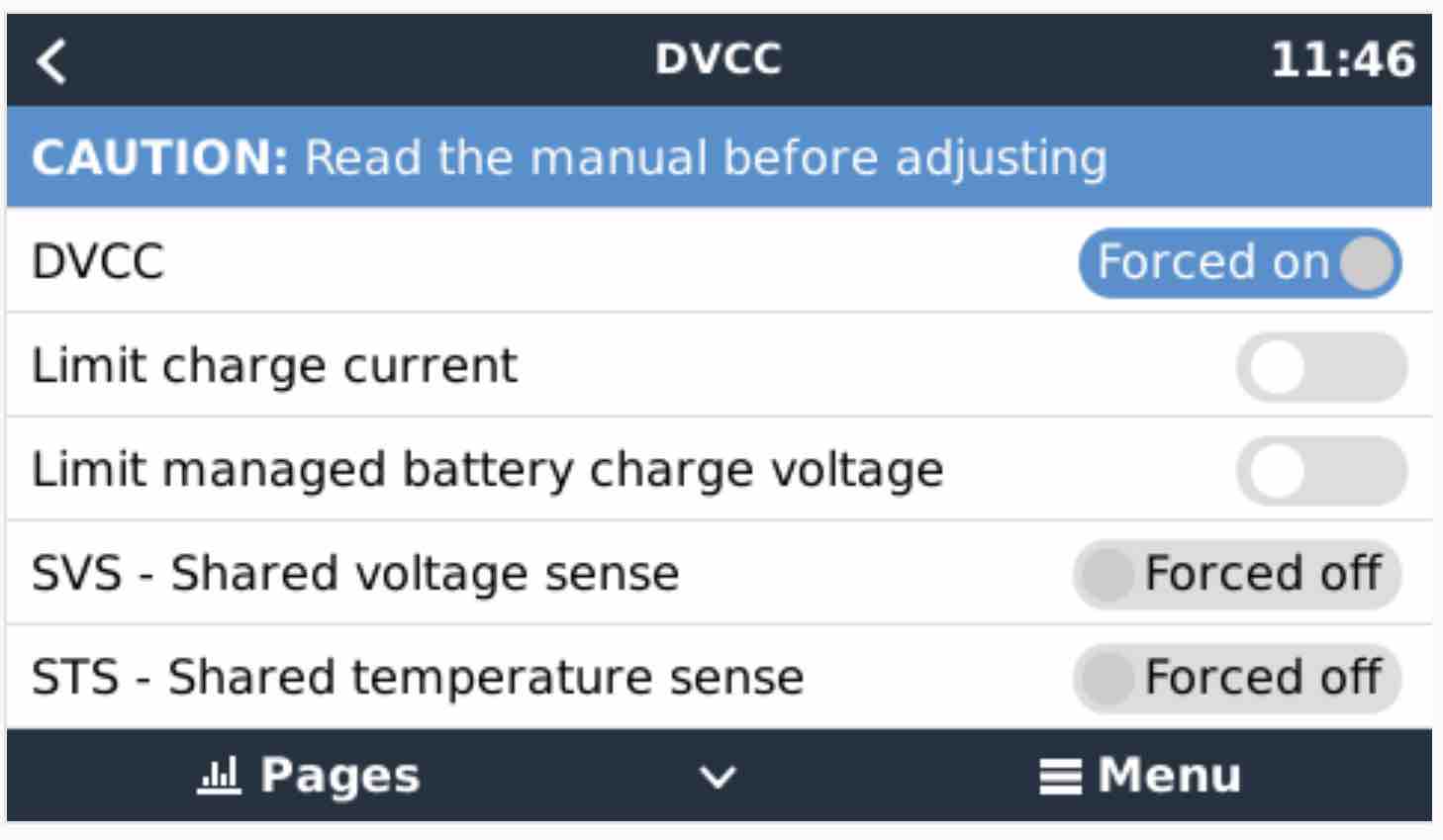
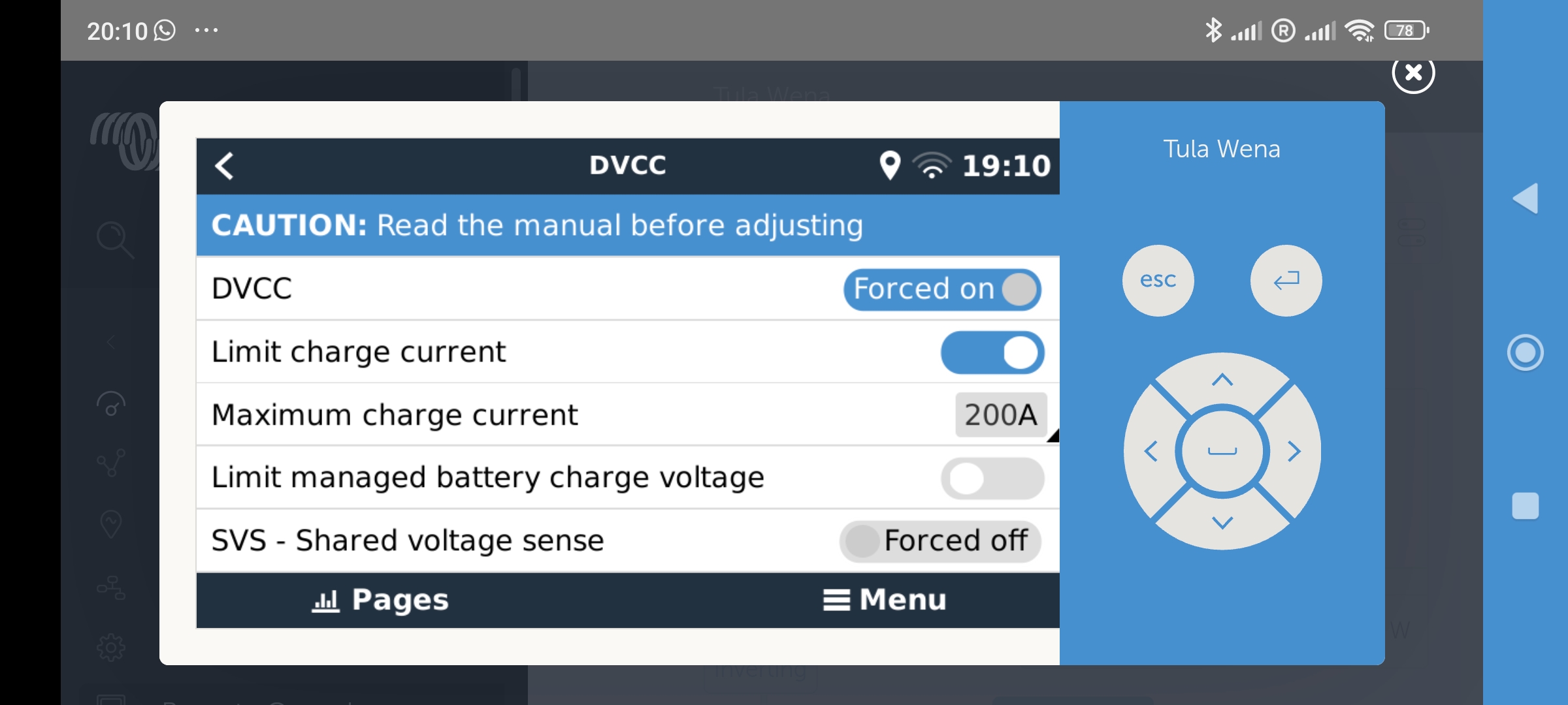
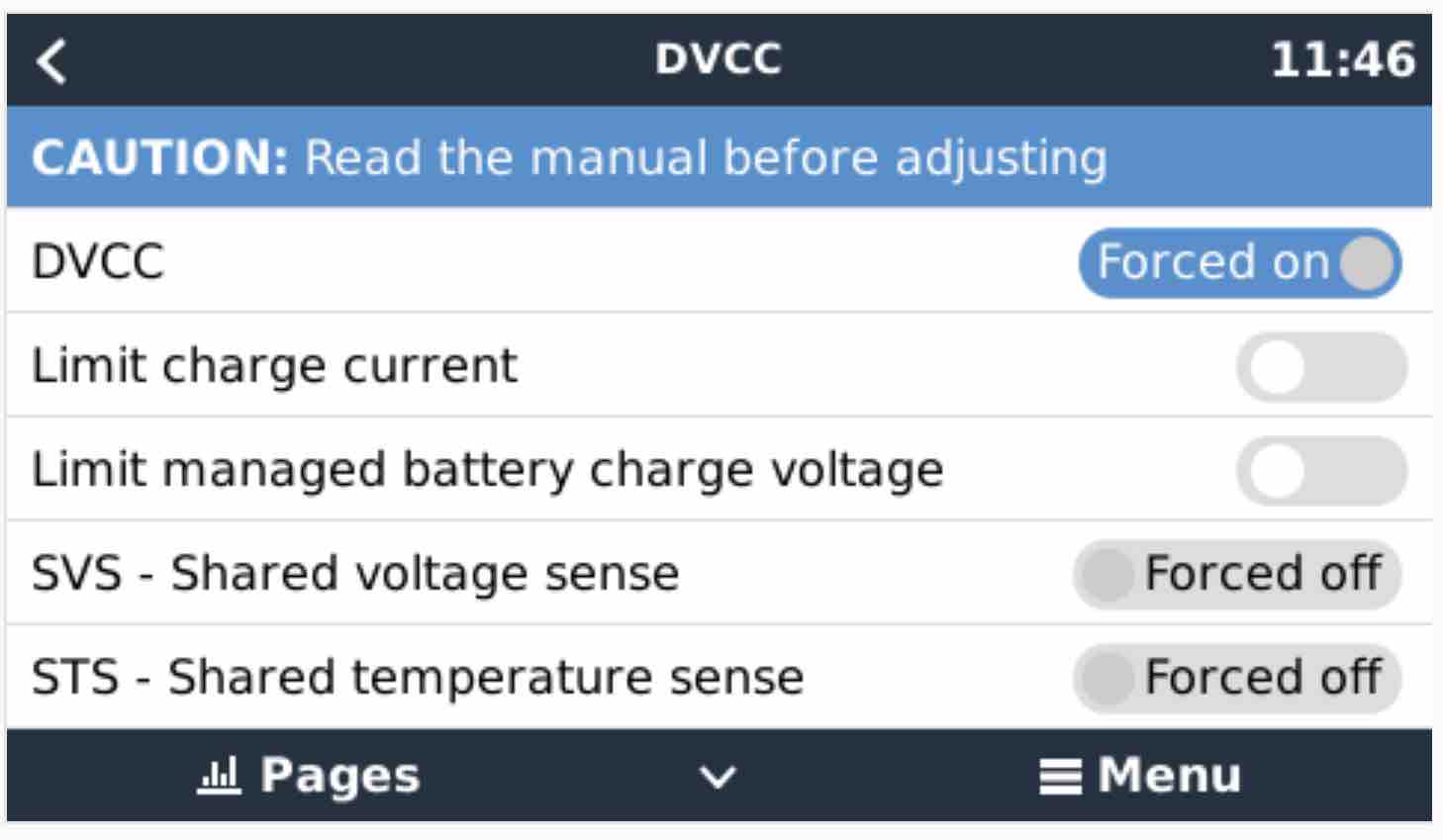
I went into the DVCC settings and confirmed I am not limiting the current there.

dvcc.jpg

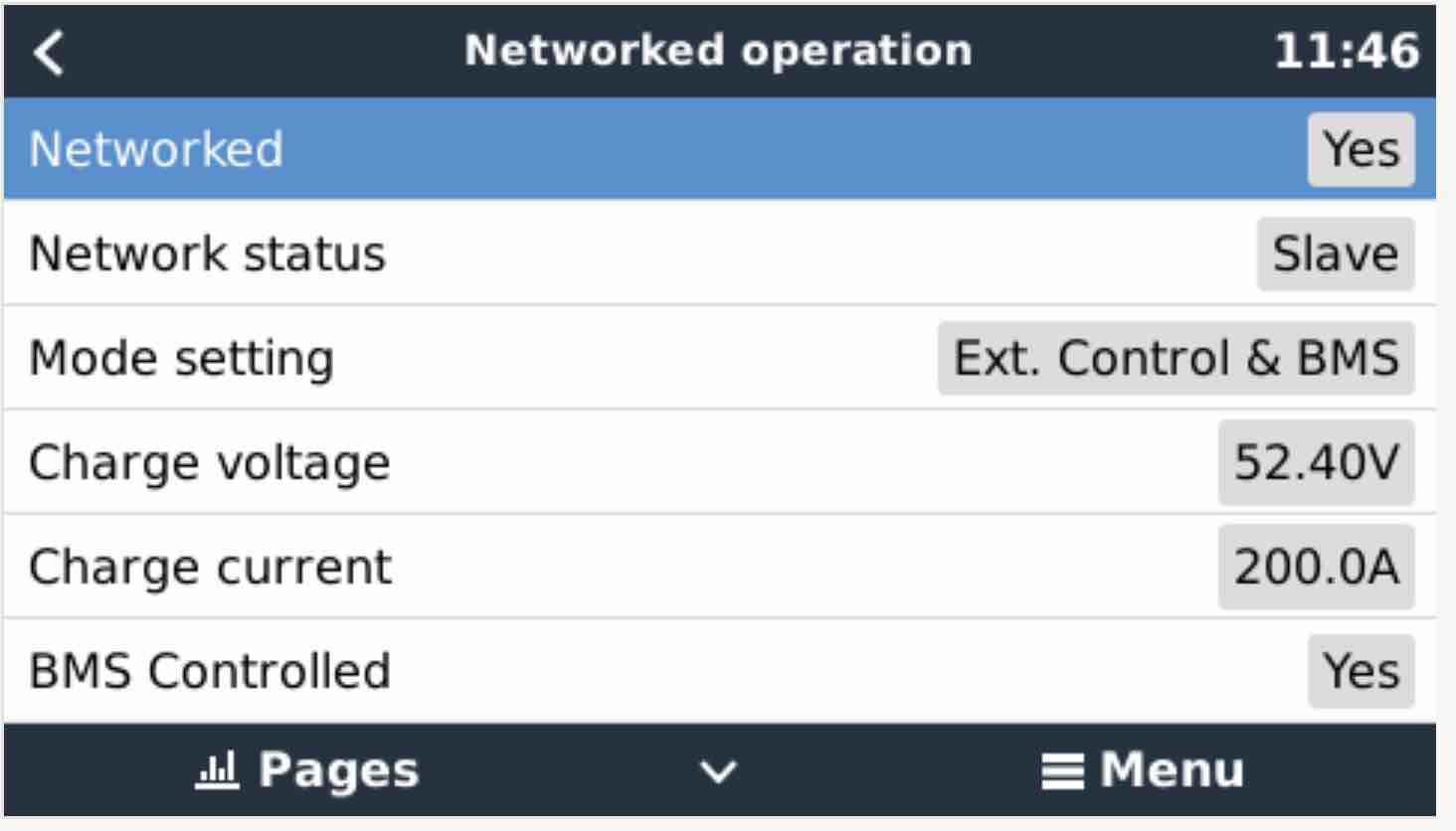
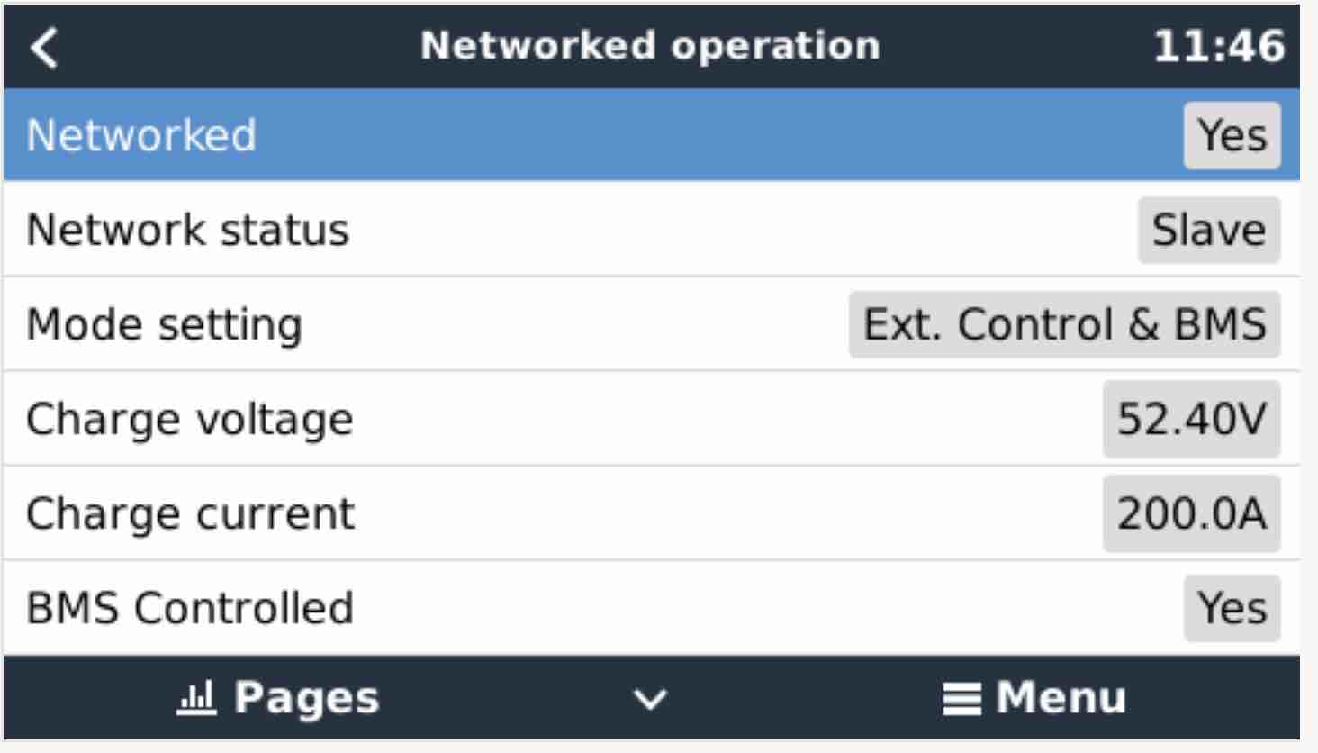
I also went into the MPPT settings and see the charge current is not limited (it's 200A because that is the max this MPPT can put out).

mppt.jpg

So I'm at a loss why the MPPT was only charging with less than 10A when the battery requested CCL was 160A.

0 Likes 0 ·
dvcc.jpg (56.0 KiB)
Alex Pescaru avatar image Alex Pescaru alaskannoob commented ·
The difference between 52.32V and 52.40V is the drop on the cables.

For sure at the MPPT output, the voltage is limited on 52.40V (set by the system), but those 80mV are the drop on the cables, so at the batteries are only 52.32V.

For sure you are on the constant voltage stage as mondeoman explained.


1 Like 1 ·
alaskannoob avatar image alaskannoob Alex Pescaru commented ·

That makes sense. It certainly behaves that way.

Thanks to everybody and especially @MondeoMan for explaining this to me.

0 Likes 0 ·
kevgermany avatar image
kevgermany answered ·

The batteries do it. They override the settings you enter.

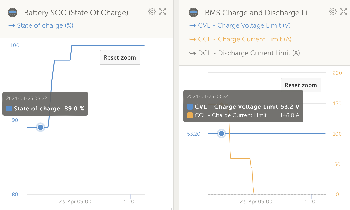
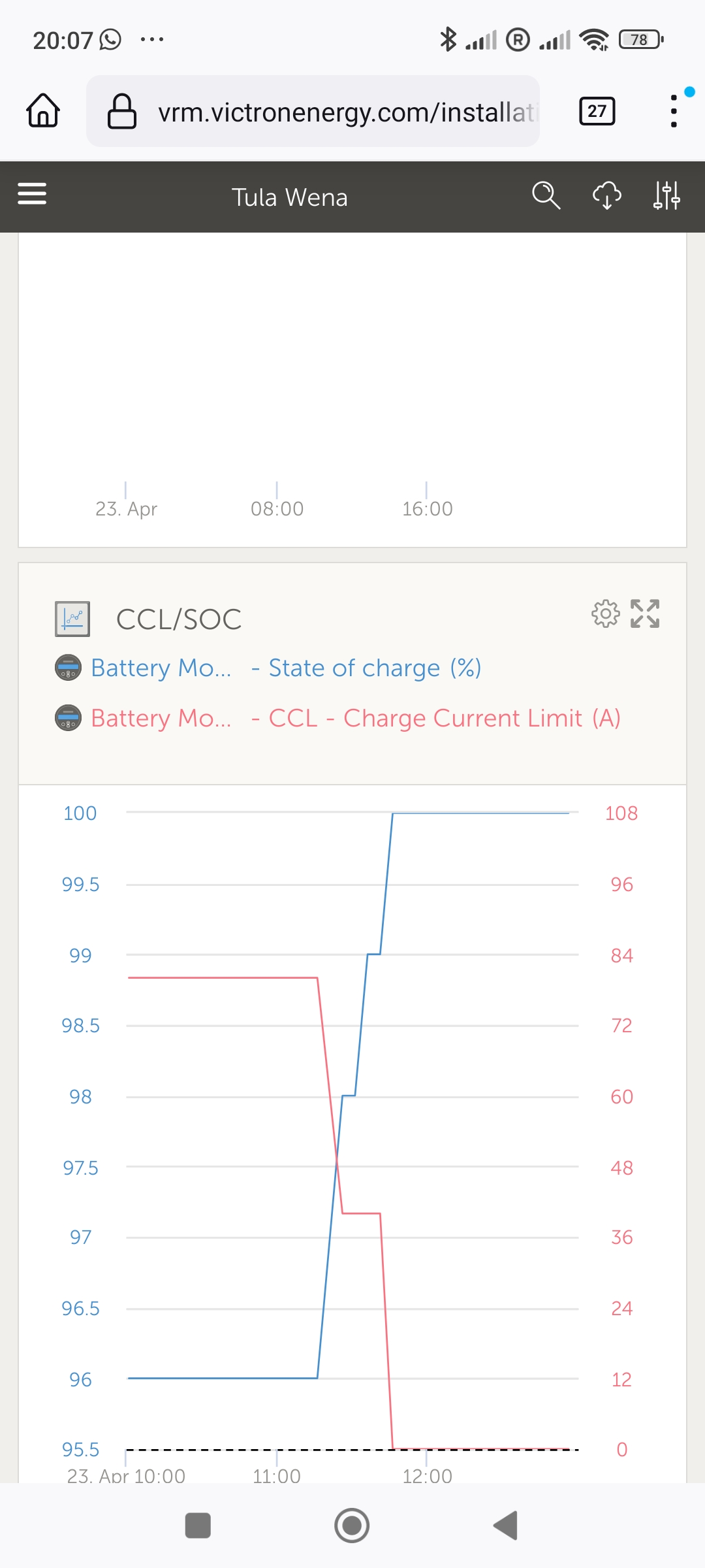
In VRM advanced try plotting SOC and CCL in a custom widget. You'll see they coincide.

3 comments
2 |3000

Up to 8 attachments (including images) can be used with a maximum of 190.8 MiB each and 286.6 MiB total.

alaskannoob avatar image alaskannoob commented ·
But if they do it, why do the batteries set a CCL of 160A while the MPPT only provides 7A (and yet tons more amps are available via PV)?


Or are the batteries setting the limits in some way other than the CCL they send to the Victron system?

0 Likes 0 ·
nickdb avatar image nickdb ♦♦ alaskannoob commented ·

Have you limited CVL in DVCC at all? This is a common cause when people fiddle with values in DVCC and set it below what the BMS wants.

Check what the battery is asking for, voltage wise, and what the MPPT and BMS are recording.

If you set a CVL limit, remove it.


0 Likes 0 ·
alaskannoob avatar image alaskannoob nickdb ♦♦ commented ·
I don't think I have. If I had, then this limit would always be there right and so I'd never see 7KW going into the batteries as I see on a good PV day when SOC is below 90%. If I had set a CVL limit I'd be complaining about my batteries never charging right?
0 Likes 0 ·
Alexandra avatar image
Alexandra answered ·

@AlaskanNoob

Ok so it ramped up, did the charging also increase? They can to some degree control what they are receiving as individuals. So may not actually need more charge? So there are some things to verify....

What voltage is the bank at and how does that compare with SOC. Some Pylons do get SOC drift BTW. Did they take more charge when you turned on the load?

{Removed incorrect statement about CCL...}

1 comment
2 |3000

Up to 8 attachments (including images) can be used with a maximum of 190.8 MiB each and 286.6 MiB total.

alaskannoob avatar image alaskannoob commented ·

No, the charge remained the same I believe.


Here is what I saw so you can see for yourself:

https://youtu.be/GsvqUdCTcXE?si=oJDcKbiNlRtw-2er

0 Likes 0 ·
Duivert NL avatar image
Duivert NL answered ·

looks completly normal to me, batterys are almost full and bms then decrease charge current

mppt's can deliver more power but there is nothing else to feed, if your allowed to feed back to grid then the surplus would go there

my grid connected ESS with pylontech's do exactly the same, charge current gets lower the fuller the batterys are only in my case mppt's will feed back surplus in to grid instead of throtteling down

20 comments
2 |3000

Up to 8 attachments (including images) can be used with a maximum of 190.8 MiB each and 286.6 MiB total.

alaskannoob avatar image alaskannoob commented ·

I agree it looks normal, I'd expect the power to ramp down as the batteries get full. But if the BMS is decreasing the charge current, I thought I would see this via the CCL dropping in the system. I thought the batteries controlled what was fed to them by issuing CCL. So I figured I'd see that number ramping down in the system, not staying at 160A while only 7A is fed into the batteries.

I'm just trying to understand how it works a bit better. Obviously something else is limiting the charge to the batteries given that CCL isn't the driving force.

Maybe it's the voltage limit that is changing that I'm not considering.

0 Likes 0 ·
nickdb avatar image nickdb ♦♦ alaskannoob commented ·
Given voltages, I would say something is off. I would meter all the various points and check you aren’t losing 1V somewhere.

You can check by switching to keep batteries charged (assuming there is grid). This inherently pushes the voltage up a bit.

It is unusual to be below cvl and above ccl for it not to charge.

0 Likes 0 ·
alaskannoob avatar image alaskannoob nickdb ♦♦ commented ·

I'm not on the grid. And the batteries are charging.

"It is unusual to be below cvl and above ccl for it not to charge."

CVL was 53.2, battery was showing 52.3 and CCL was 160A and batteries were being charged with less than 10A.

You're saying this is abnormal?

I have DC loads coming off the bus bar, powering an Orion, any chance that has something to do with it?

Also, Victron advertises that they will charge these Pylontech batteries at less than the CVL requested by Pylontech because Victron believes Pylontech asks for too high a charge voltage. So that may be what you're seeing.

From the Victron Compatibility Guide:

"When DVCC is enabled, the battery (via the CAN-bms) is responsible for the charge voltage. The Pylontech battery requests a charge voltage of 53.2V. We have however found that in practice this is too high.

The Pylontech battery has 15 cells in series, so 53.2V equates to 3.55V per cell. This is very highly charged and makes the system prone to go overvoltage.

It should also be noted that a LiFePO4 cell stores very little additional energy above 3.45V.

For this reason we opted to override the BMS and cap the voltage at 52.4V. This sacrifices almost none of the capacity and greatly improves the stability of the system."

0 Likes 0 ·
nickdb avatar image nickdb ♦♦ alaskannoob commented ·

For 8 batteries, I would suggest that is a bit low, but what is the ambient temp?

The video shows that the MPPT is ramping fine for loads, so that implies that is all the batteries want, not knowing enough I can't be sure.

If I look at some of mine at 90% - they take 30 minutes more to hit 100% and drop CCL to 0, Before that voltage is actually lower than your for the same SOC and it charges (fewer batteries) at 50A.

So I suspect, your SOC is actually off.

At the same voltage, my pack is at 97% and CCL has dropped, yours is unchanged.

Perhaps a combo of SOC drift and temp and a sprinkling of minor imbalance?


screenshot-2024-04-23-at-170139.png

screenshot-2024-04-23-at-170256.png

0 Likes 0 ·
alaskannoob avatar image alaskannoob nickdb ♦♦ commented ·

Battery temp was likely somewhere around 40-45F.


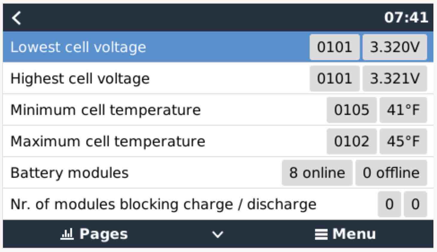
My cell balances have been within .002 routinely although I didn't check yesterday.

Here is the balance currently:

balance.jpg

I am really just wondering why the CCL limit is 160A, the PV could provide up to 40A at the time (which I demonstrated by adding the space heater load to show available PV) and yet less than 10A was being supplied to charge the batteries.

I would expect with 160A CCL that the system would try to give the batteries up to 160A of current to charge. But something is limiting that amperage.

It may be that I'm just not understanding charging and voltage because at certain voltages you have to supply less amps otherwise it raises the voltage. So while the batteries are saying they can accept 160A, that would depend on what voltage is used to charge, so maybe that is my confusion.

0 Likes 0 ·
balance.jpg (59.7 KiB)
Show more comments
Fideri avatar image Fideri alaskannoob commented ·
@AlaskanNoob

Where did you see CCL of 160A? My understanding of what I saw in the video is not the realtime or effective CCL. It's a mere setting. Think of it as the "maximum CCL". Not necessarily the "effective CCL".

Looks completely normal to me.

F.

0 Likes 0 ·
alaskannoob avatar image alaskannoob Fideri commented ·

In the beginning when I went to the parameters page, the CCL is at 160A. That isn't a setting. That number changes as the Pylontech batteries change it automatically.

When the batteries are colder, the CCL and DCL numbers will drop. And as the battery gets more full (above 90%) the CCL will drop.

I don't set anything. That's just reflecting what the batteries want via DVCC and they do change real time.

ccl.jpg


I'm unfamiliar with "effective CCL" but I think you're right. I'm guessing the batteries say we can take as much as CCL, and the MPPT says "yeah, but this lower current will work better" and that number just isn't shown anywhere I guess, other than seeing what current is supplied.

0 Likes 0 ·
ccl.jpg (44.3 KiB)
kevgermany avatar image kevgermany ♦♦ alaskannoob commented ·
This value is not the value that's being used. It's actually a max that you have configured, not the batteries. A single US5000 will set a limit of 100A or more. With 8 batteries that aren't full, expect to see 800A in VRM. Unless it's cold, that is.


Check in VRM advanced as I said before. This will show the limit that's being used.
0 Likes 0 ·
kevgermany avatar image kevgermany ♦♦ kevgermany ♦♦ commented ·

1000017020.jpgHere's one from my boat, 4xUS5000.1000017019.jpg

0 Likes 0 ·
1000017019.jpg (250.6 KiB)
1000017020.jpg (351.2 KiB)
alaskannoob avatar image alaskannoob kevgermany ♦♦ commented ·

That is incorrect.


It is a dynamic value that changes automatically with no input from me, because the battery provides this value to the Victron system in DVCC and adjusts it accordingly.

I don't use VRM but in Victron Console I have no limit to the charge set in the DVCC menu (unlike in your set up) and my MPPT has no charge limit set up.

I watch the CCL value change automatically in real time. On very cold Alaska days I monitor that page to see what the batteries say the CCL is before I turn on the generator, for example, while I warm the solar shed. I sit there and wait until that CCL value rises to the appropriate number that allows me to turn on the generator without providing too much current (I'm using a Chargeverter). So I know that value is from the batteries and is not set by me and is dynamic.

dvcc.jpgmppt.jpg

0 Likes 0 ·
dvcc.jpg (56.0 KiB)
Show more comments
Fideri avatar image Fideri alaskannoob commented ·

I think @kevgermany is right. I can't grab a screenshot right now but mine looks like his. The CCL figure never changes, regardless of SOC. But my chargers vary production depending on SOC and/or the weather.

F.

0 Likes 0 ·
alaskannoob avatar image alaskannoob Fideri commented ·
I don't have VRM and only use Victron Console locally, but I am positive you both are incorrect on this point.


It is not a setting. Again, this is in DVCC.

I have never set a charge limit. And it changes automatically based on temperatures and SOC and such, because the battery is setting this limit and adjusting it in the system.

DVCC.

0 Likes 0 ·
Show more comments
Duivert NL avatar image Duivert NL Fideri commented ·

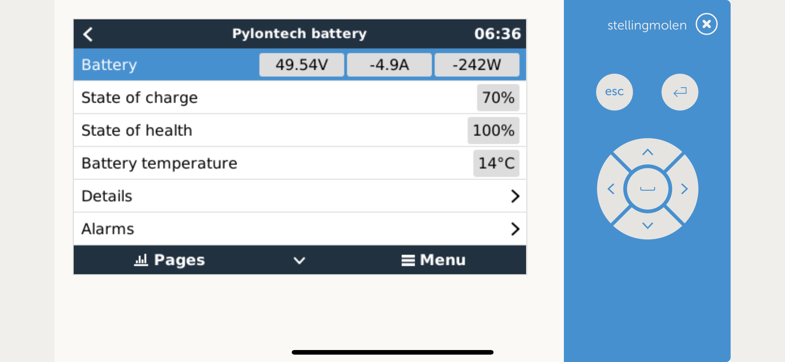
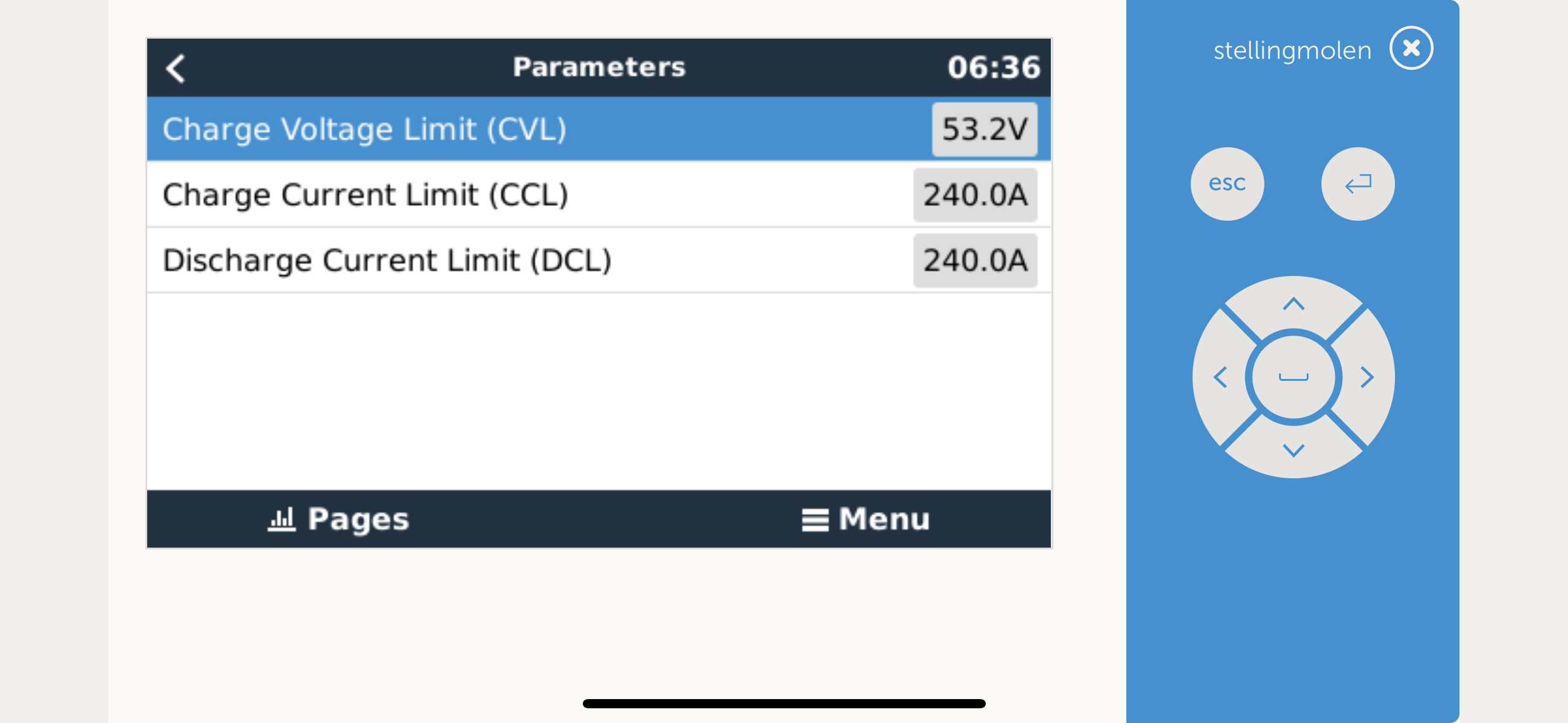
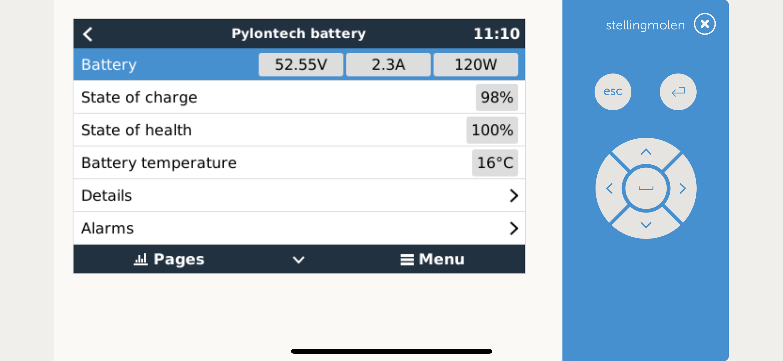
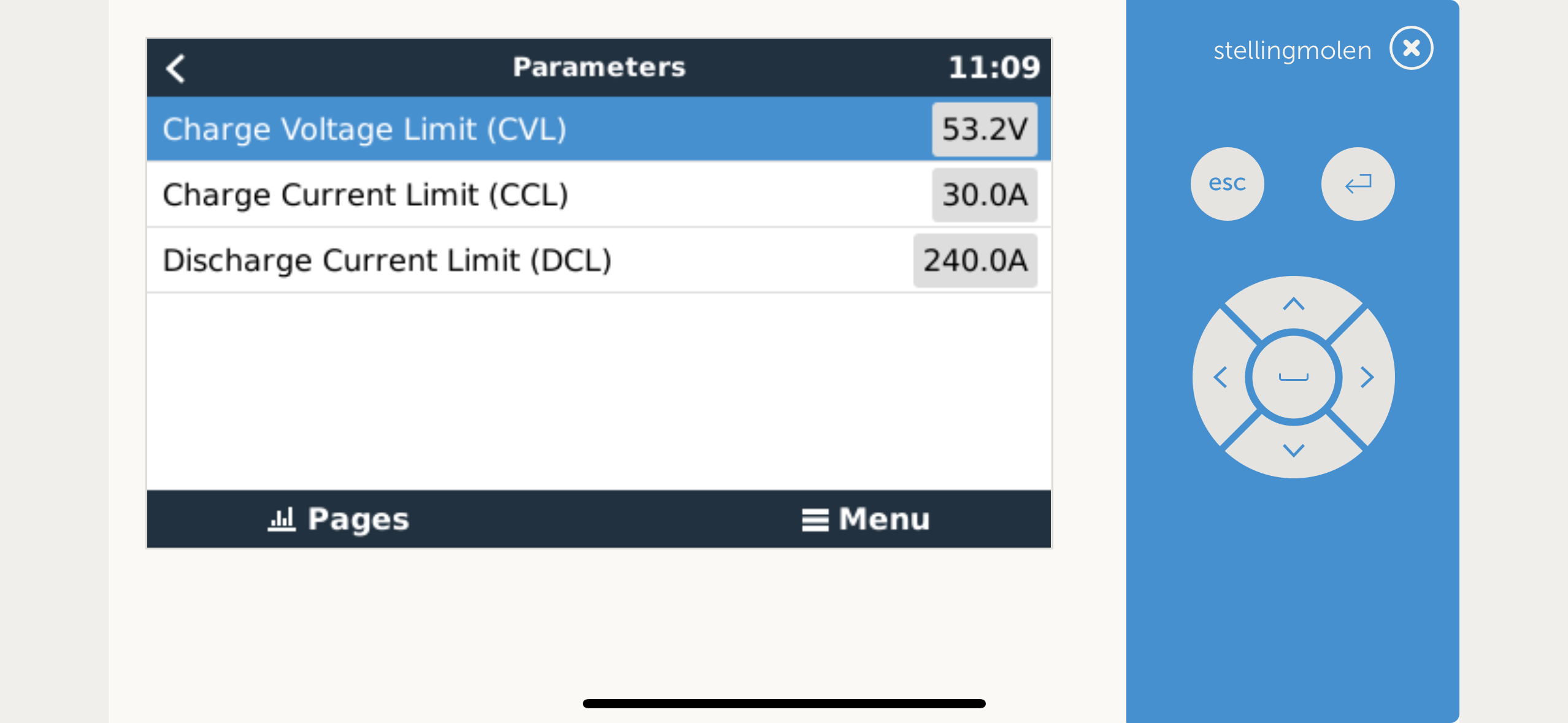
I will make some screenshots today to proof the pylontechs will change the CCL in DVCC

Here are the screenshots:

img-6328.pngImage Caption

img-6327.png

img-6331.pngImage Caption

img-6330.png

0 Likes 0 ·
img-6328.png (284.3 KiB)
img-6327.png (252.2 KiB)
img-6331.png (281.6 KiB)
img-6330.png (248.2 KiB)
Show more comments

Related Resources