question

ernstsl avatar image
ernstsl asked

Added BMV-712 to system with Smart BatteryProtect 12/24V 65A; where to connect black wire BP?

Hi everyone,

Try to use proper english, hope you experienence this while reading ;-)

I searched for an answer, also within this forum, but did not find it, so therefore this new question.

I would like to know on which terminal I mount the black wire of the BP? It was (and is) mounted at the place you see 20230925-145111.jpeg on the picture, at the negative bar. Since I added the BMV to the system, should I connect it to the added shunt instead? And if so, which of the two connections? Or perhaps it does not matter?
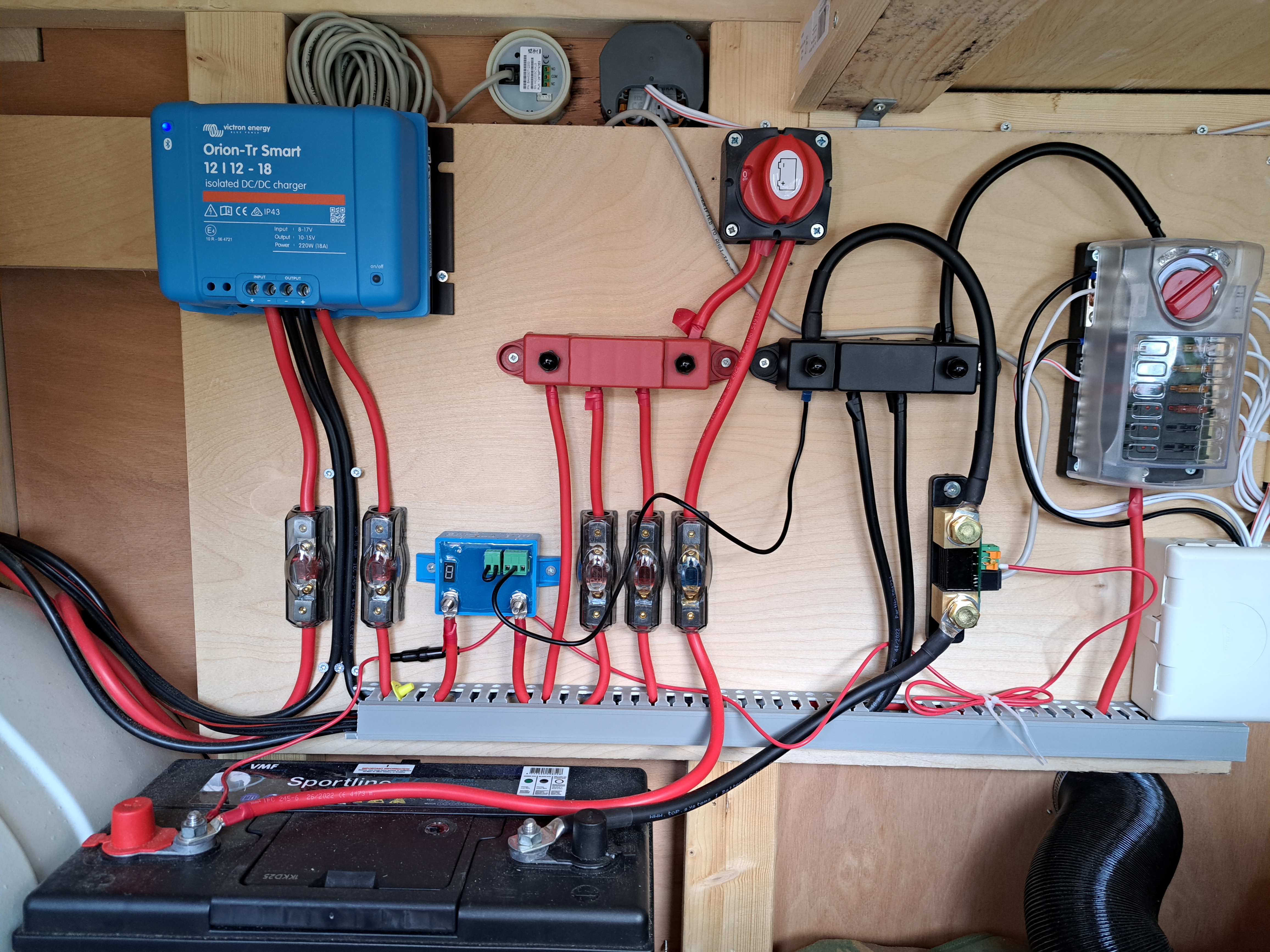
And, I’m not sure, but do the two devices interfere with eachother? They both monitor the volts of the battery and can it disconnect from the net if the voltage is to low, if I am correct? Can this cause some problem?

Thanks!!

Ernst

Dordrecht, NL

BMV Battery MonitorBattery Protectwiring
2 |3000

Up to 8 attachments (including images) can be used with a maximum of 190.8 MiB each and 286.6 MiB total.

3 Answers
Justin Cook avatar image
Justin Cook answered ·

The BatteryProtect's black negative return wire is already connected to the shunt, since it's connected to the busbar which is connected to the "loads and chargers" side of the shunt. Your installation of that is fine as it is, at least as directly asked. You must not connect the negative return wire directly to the battery, as that would bypass the shunt and therefore your battery monitor would not be able to measure its current consumption.

The BMV does not disconnect the batteries if the voltage goes low - it is a battery monitor, not a battery controller.

Please keep in mind that the BatteryProtect is unidirectional in operation - it appears that it's connected on the output of your Orion-Tr Smart (also, why? there is no need for it there) and it looks an awful lot like it's connected improperly, though it is difficult to tell from the photo angle. If using it as a charge disconnect, then as per the user manual it must be connected with the charger output running to the "input" side of the BatteryProtect and the battery (or in this case, the positive busbar) on the "output" side, to avoid malfunction and/or failure.

I strongly advise thoroughly reading all product installation and user manuals again, especially as you're adding components, to ensure that everything is connected correctly and appropriately, and/or consult a reputable and experienced systems installer in your area to double-check the installation and correct anything that may be found wanting.

3 comments
2 |3000

Up to 8 attachments (including images) can be used with a maximum of 190.8 MiB each and 286.6 MiB total.

matthias-nagel avatar image matthias-nagel commented ·

First, I also was confused by that kind of installation, but then it appeared to me that this battery protect might be in place to protect the battery against overcharging. The Battery Protect is not only used disconnect a battery from loads but can also be used to disconnect chargers from the battery.

As it has been this way before and the OP did not change anything there, I assume that the original installer used it that way.

0 Likes 0 ·
Show more comments
matthias-nagel avatar image
matthias-nagel answered ·

Theoretically, the black wire (GND) of the Smart Battery Protect should be as close as possible to the negative pole of the battery for accurate voltage measurements.

There will also be a small voltage difference across the [moderator edit: BMV-712 shunt]. Optimally, you would connect GND of the Smart Battery Protect to the [moderator edit: Loads & Chargers -] terminal of the [moderator edit: BMV-712 shunt] (i.e. at the bottom in your photo) or [moderator edit: removed incorrect advice]

However, I would deem the difference in voltage measurement negligible. In particular, in case you need to replace the battery it make maintenance more easy, if less wires are directly connected to the battery. Hence, for reasons of practicability and would keep it the way it is.

1 comment
2 |3000

Up to 8 attachments (including images) can be used with a maximum of 190.8 MiB each and 286.6 MiB total.

Justin Cook avatar image Justin Cook ♦♦ commented ·

For future, please be sure to read and understand all appropriate user manuals of the products you're offering advice about before offering advice, as there were multiple incorrect recommendations in your original reply.

0 Likes 0 ·
ernstsl avatar image
ernstsl answered ·

Dear Matthias,

Thank you very much for your swift and clear answer! I think I will move it to the bat-terminal of the smart shunt as you suggested. Not direct at the terminal of the battery itself, which could be a nuisance when removing the battery for winter etc, but only a schot cablelenght away ;-)

Thanks!

Ernst

1 comment
2 |3000

Up to 8 attachments (including images) can be used with a maximum of 190.8 MiB each and 286.6 MiB total.

Justin Cook avatar image Justin Cook ♦♦ commented ·

Please do not do this. Nothing should be connected to the "battery" side of the shunt except the battery, as detailed in the battery monitor's user manual, otherwise your battery monitor cannot "see" it, and will not measure it, and will therefore be inaccurate.


0 Likes 0 ·