question

solardude avatar image
solardude asked

120/240 Split Phase Diagram Question

Admittedly, this is my first Victron install, and I appreciate all the help so far. I have my system up and running, but have not load tested it yet. I have 120V on each leg and 240V when tested from L1 to L2. Everything seems to be working as expected.

My question is about the AC wiring, and if it is OK to wire it as my diagram shows in the attached pic. The isolation transformer is about 1 meter from the Quattro's. The mains input is about 4 meters from the inverters. I wasn't sure if I need jumpers between the inverters for the neutral and the PE (both input and output), or if a home run for each as illustrated is OK. I thought it looked very clean with individual home runs, so that is how I wired it.

I have only worked with inverters that have built in 120/240 in the past, so the wiring on these is a bit different than I'm used to. I'm trying these out on my own boat, because I really like the custom programming and the integration with other systems. Thanks again for the assistance, any input is much appreciated.
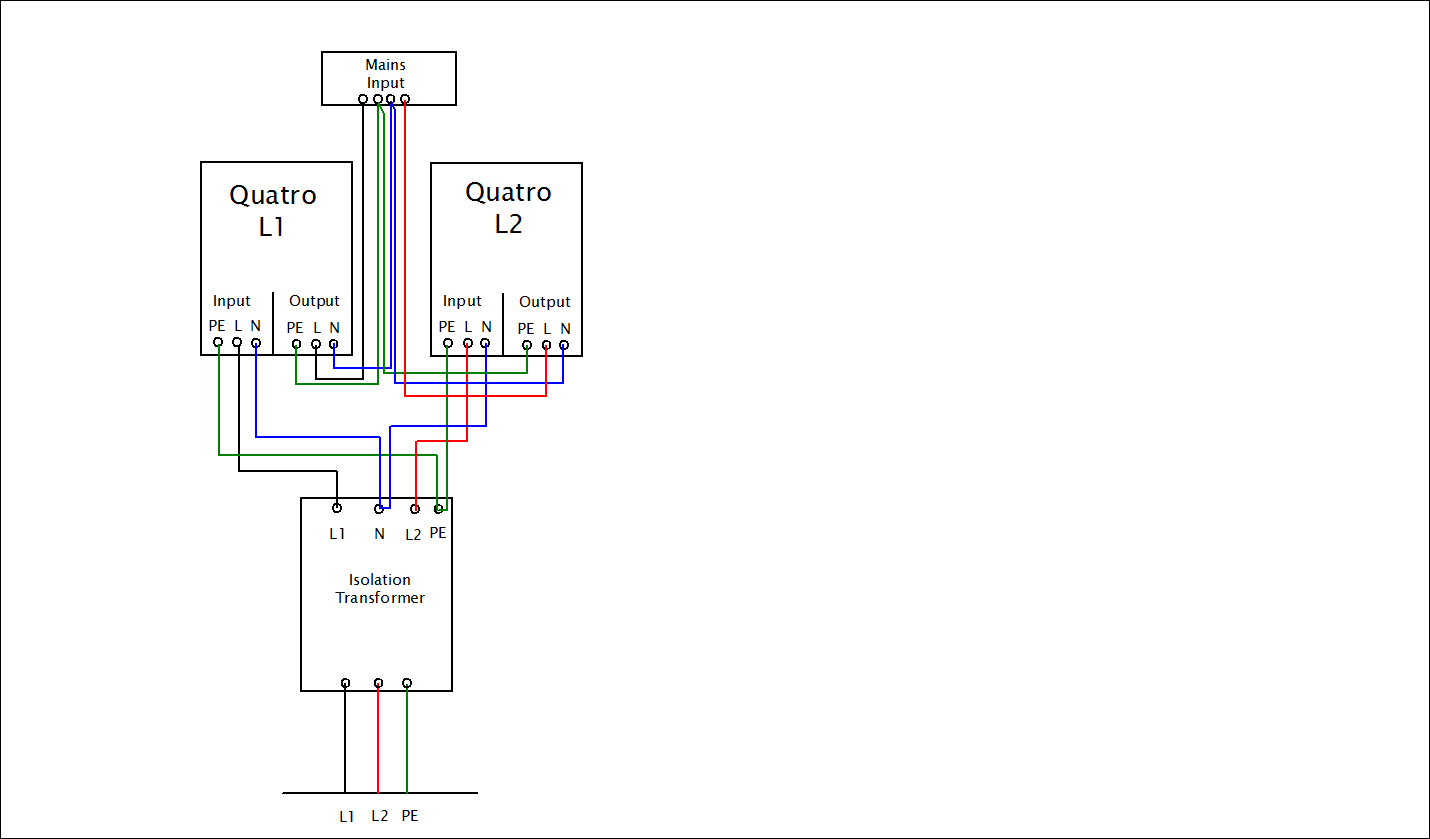
wiring
2 |3000

Up to 8 attachments (including images) can be used with a maximum of 190.8 MiB each and 286.6 MiB total.

2 Answers
Paul B avatar image
Paul B answered ·

Hi I have never installed this type of system so please dont take my word for this.


Looking at your drawing I would have thought that the L1 and L2 inverter to me looks like its reverse wired. the in power should go to the ac1 in (input) and the out power to AC1 out (Output)


thats unless you have marked the drawing incorrectly as the Isolation transformer is the in power and the Mains in is the power to the boat ????

4 comments
2 |3000

Up to 8 attachments (including images) can be used with a maximum of 190.8 MiB each and 286.6 MiB total.

solardude avatar image solardude commented ·

The isolation transfomer is between the shore power inlet and the inverters. It feeds both inverters, then goes from inverters to the main input breaker on my panel.

I also didn’t draw all breakers and some other details, just the main wiring.

For now Im only using AC1 input and AC1 output. I’ll add the genset circuit later on AC2 input.

0 Likes 0 ·
Show more comments
solardude avatar image
solardude answered ·

The isolation transfomer is between the shore power inlet and the inverters. It feeds both inverters, then goes from inverters output to the main input breaker on my panel.

I also didn’t draw all breakers and some other details, just the main wiring.

For now Im only using AC1 input and AC1 output. I’ll add the genset circuit later on AC2 input.

2 |3000

Up to 8 attachments (including images) can be used with a maximum of 190.8 MiB each and 286.6 MiB total.