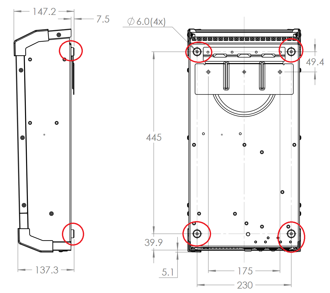
Anyone got measurements (for CAD) where exacly are the two botton screw holes that are used to secure Multiplus into wall? I have the top mounting plate hole locations only.
- Home
- Anonymous
- Sign in
- Create
- Spaces
- Grafana
- Node-Red
- Unsupported topics
- Questions & Answers
- Modifications
- Communauté francophone
- Deutschsprachiger Bereich
- Preguntas en Español
- Explore
- Topics
- Questions
- Ideas
- Articles
- Badges
question
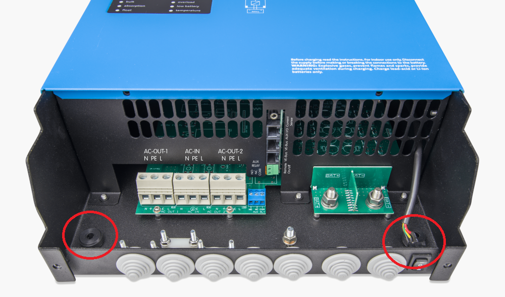
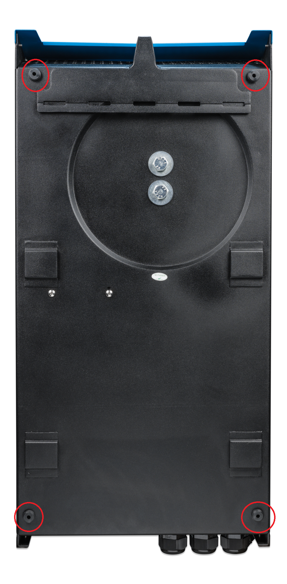
Do you mean this?

(picture of a 5kVA unit)

(picture of a 15kVA unit)

It would be necessary to know which model specifically of MPII you are referring to? Either way this information is in the last few pages (the appendix) of the respective manual. Example below:
https://www.victronenergy.com/upload/documents/MultiPlus-II_230V/32424-MultiPlus-II___Quattro-II_120V-230V-pdf-en.pdf
I have the 3000VA model. Maybe they are the 4x 6mm holes that are 445mm and 230mm apart where the rubber feet are screwed in?
Did you look at the product page? There are documents and 3D files available.
https://www.victronenergy.com/inverters-chargers/multiplus-ii#enclosure-dimensions
I'm confused
What exactly are you looking for? Can you make a picture/screenshot?
When Multiplus is mounted vertically on wall with the included top bracket, it is supposed to be fastened to wall also with two botton screws. Atleast that's what I think, no idea where those bottom screw places are.
Related Resources
Additional resources still need to be added for this topic
question details
83 People are following this question.
