question

nebulight avatar image
nebulight asked

Raspberry Pi Analog inputs (Tank input)

I'd like to reopen discussion on this topic. I'm a novice and freely admit that I really don't understand all aspects of how to get this to work. So I may be totally off with this so please correct me if I'm wrong. I've read this thread:

https://groups.google.com/forum/#!msg/victron-dev-venus/mejgJbMjU34/yogWAU5wCAAJ;context-place=forum/victron-dev-venus

I purchased the same board as what's here, the Expander Pi with the mcp3208 12-bit ADC.

From reading this, I'm a bit confused how to wire this up. In that thread, they point to the reference voltage of 1.8v. However the expander pi has a reference voltage of 4.096. But in other threads, they talk about a reference voltage of 5v. I also see the schematic of the BBB Cape and it says 5v as well:

I'm not sure what is correct or if the reference voltage even matters since both are 12-bit ADCs, the reference voltage shouldn't matter as it's just reading the resistance of the sender. But then I'm confused on how to wire this up with the Expander Pi. Anyone who has this board, would they care to share their setup, possibly with photos or diagrams? I'd appreciate it.

tagging @WKirby as you've always been super helpful!

Venus OSRaspberry Pitank monitor
tank.png (51.9 KiB)
1 comment
2 |3000

Up to 8 attachments (including images) can be used with a maximum of 190.8 MiB each and 286.6 MiB total.

jimmyendt avatar image jimmyendt commented ·

Hello,


I'm looking to connect resistive ( 0 -190 ohm) tank level sensors to my raspberry pi venusos setup. I've searched everywhere, but are still a bit lost in this matter.


As I understand in the comments above you need a ADC converter (analog to digital) a mcp2308 chip sounds like the chip that worked for others users on this great forum.

I also found the awesome HAT Rob Duthie has developed and think that would be an amazing addition to my setup. I'm not technical enough to build it myself and have allready asked where to buy:)


This would seem like a plug and play option right?


my questions:

1. About the volt ref. 1.8 as I understand this is something you can do in the software, but this would make it less accurate, correct?

2. to add the 0 - 190 Ohm tank level senders to the ADC chip, I'm confused. Do you need additional hardware to make it work? Resistors, capacitors?

3. If the answer to 2 is yes, where can I find additional info? ( despite all the information above my mind is still not able to understand it fully)


4. would a HAT like the one below work ? (there is a MCP2308 chip)


https://www.tindie.com/products/cburgess129/high-precision-12-bit-adc-hat-for-raspberry-pi/

this one you can set the Vref to 3.3 of 5. volts?


On that site there is also a simpler version

https://www.tindie.com/products/cburgess129/12-bit8-channel-adc-hat-for-raspberry-pi-v30/ 

0 Likes 0 ·
27 Answers
nebulight avatar image
nebulight answered ·

HOLY COW! I've gone from knowing pretty much nothing about this kind of stuff to getting it to actually work!! I was really thrown off the by the schematic above. You are feeding 5V to the tank sender, but the input to the ADC thanks to the resistors brings the voltage down so you actually need a voltage reference of 1.8v on the ADC top row second pin. I ordered an expander pi with a vref on board to 1.8v, but it was damaged in shipping. While I waited, my curiosity got the better of me, so I bought some wire, breadboards and a physical ADC chip and made this mess:


I took the 3.3v pin on the pi and made a voltage divider with two resistors (56kohm and 68kohm). The orange wire in the middle of the two resistors went to the ADC vref pin as that's around 1.8v (close enough for my testing, hopefully the vref chip will be more accurate). Then to get the signal wire to the ADC, I just copied the schematic above. I fed 5v to a 680 ohm resistor, then connected that to a 10kohm resistor, then a signal wire (in green) to the ADC port 5 (tank 1). I then hooked up the signal wire (red exiting to the left) to the tank sender. I loaded the ADC dbus driver from the post above and ran the commands. Rebooted the pi and my tank sender was showing 100%!!!! I lowered it to around half and was around 50-55%! Down to almost empty and it was at 4%! IT'S WORKING!!!!! The only thing that is odd (and I think it's a feature of the OS) is that when you lower the tank level, it's pretty quick. However when you fill the tank and raise the level, it SLOWLY increases. I think this is to prevent sloshing around (I think I read that on another post). So this will be a problem when I try to fill my aux diesel tank in my camper van, but that's something I can work around. I plan on making a full write up/video for youtube to help people like me who are clueless. Huge thanks to @Rob Duthie for his help with my beginner questions over email. And big thanks to Victron for making your software open source and all the users on the google group that did all the heavy lifting!


Your browser does not support HTML5 video.


18 comments
2 |3000

Up to 8 attachments (including images) can be used with a maximum of 190.8 MiB each and 286.6 MiB total.

Ralf Klüber avatar image Ralf Klüber commented ·

Any configuration on the rPi? How does Venus OS know which GPIOS being used?

0 Likes 0 ·
nebulight avatar image nebulight Ralf Klüber commented ·

You need the ADC chip as you don't feed the information directly to the pi. It's easier to just buy a HAT but you can use this to wire up a raw MCP3208. Ignore the temp sensor and the vref voltage as that must be 1.8v. See the above post.

The venus software knows which ADC inputs it uses for each. Since this is based of the beaglebone board which is in the Venus GX, it's as followed:

ADC1: Not Used

ADC2: Not Used

ADC3: Tank 3

ADC4: Temperature 2

ADC5: Tank 1

ADC6: Temperature 1

ADC7: Tank 2

ADC8: No present on the beaglebone so not used

0 Likes 0 ·
1568061747768.png (589.3 KiB)
5teve avatar image 5teve nebulight commented ·

@nebulight - could you advise if anything would need to change to use the MCP3008 instead of the 3208 - the 3008 is a 10 bit chip.. and available locally to me.

Thanks

Steve

0 Likes 0 ·
seekingdave avatar image seekingdave nebulight commented ·
Hi, I appreciate this is a very old thread but was hoping you might give me a little guidence on this. I have 4 resestive type tank sensors already installed in my camper tanks. I was using home assistant but have changed to Venos OS Pi 4b, I have the pi and OS up and running and connected to my shunt / invertor and solar but I would like to put in the 4 tank sensors as well. Reading the thread and replies I can see I could add three sensors, is it possible to add 4? also I can not get access to the original thread for the drivers etc. any help or advice on how to set this up to use these senders with this system would be amazing. Thanks Dave C
0 Likes 0 ·
Rob Duthie avatar image Rob Duthie seekingdave commented ·

Having spent weeks trying to get this to work with a lot of help from Rob Duthie I was finally successful in getting the analog ports to show up on both a Raspi3 and a Raspi 4. I thought I should document exactly what I did in case it helps someone else (no guarantees!) . I have literally documented every tiny step because I did essentially the same things many times in a different sequence and it didnt work. I still cannot get the expander pi board to work and am resorting to a bare mcp 3208 chip and a breadboard:


  • Download Venus OS image and burn to micro SD card
  • While still in windows (or your desktop OS) copy the correct mcp3208.dtbo file (see thread above) to the overlays folder on the micro SD card
  • Edit the config.txt file and add the following lines in the [All] section

dtparam=spi=on

dtoverlay=mcp3208:spi0-1-present

  • Insert the micro SD card in the Raspi and boot up connected to your network by ethernet
  • Find the IP address of the Raspi (I use Victron Connect bluetooth)
  • Open the remote console on your desktop
  • Setup superuser access and password and enable SSH
  • Using Winscp edit the dbus-adc.conf in the etc/venus folder to read as follows:


device iio:device0

vref 1.8

scale 4095


tank 0

tank 1

tank 2

tank 3

temp 4

temp 5

temp 6

temp 7


make sure there is a carriage return at the end of the text. It didn’t work until I added this although it might have been something else that made the critical difference……..


  • Reboot
  • Check for analog ports in the I/O page of settings
  • Continue to setup the system using setup helper addfing Guimods etc. All the tanks and temperatures should show up on the GUI.


0 Likes 0 ·
hugyourewoks avatar image hugyourewoks commented ·

Hey @nebulight I'm pretty new to victron on raspberry pi. I've played around on pi before, but in a general way. I have a camper van and want to add two tank level sensors to my system and have Venus Os monitor them. You used a pi 3+ right? Which HAT do you recommend? The HAT takes the resistance measurement from the sensor and allows the OS to view correct? I could just buy a Venus GX, but I don't have any other victron components, so the plug and play functionality with my solar charge controller and inverter won't work. That's, okay, I just like the Venus OS look and ease of use with my onboard LTE router and VRM upload. Is the HAT option easier than the breadboard, or are they complimentary? I love learning about stuff like this so, I don't mind learning about all that.

This is the sensor I'm going to get.

KUS USA SSS Fuel & Water Level Sensor, 10" https://www.amazon.com/dp/B00Y831RM0/ref=cm_sw_r_cp_apa_i_F8.4Db846306H

0 Likes 0 ·
nebulight avatar image nebulight hugyourewoks commented ·

To answer your questions, yes I'm using a 3+. The problem with a HAT is most available don't have the correct vref so you'll have to modify it. You'll also need to add the correct resistors in order to make it work. I've been playing around with the expander pi unit because that has the correct ADC, but will all the modifications it would require, I'd recommend just buying the ADC chip, some blank PCB boards and solder everything yourself. The breadboard was just for testing, wasn't meant to be a permanent install.

With that said, if you don't have any other victron components I'm not sure it's a good use of your time to have a GX device only for tank monitoring. Blue sea is coming out with a compact tank monitor that looks pretty nice and is reasonably priced. https://www.bluesea.com/products/1739/Mini_OLED_Tank_Meter_-_Yellow They also have a 4 tank monitor, but it's more expensive than buying 4 of these.


0 Likes 0 ·
hugyourewoks avatar image hugyourewoks nebulight commented ·

@nebulight True, I don't have Victron components, but I'm thinking of adding a BMV 712 to monitor voltages and current via the MK3 USB. I think the remote monitoring is worth the trouble plus a Pi is cheap. Hardware side, I can just plug the ADC 3028 into the Pi pins and then the sensor into the right channel correct?

0 Likes 0 ·
nebulight avatar image nebulight hugyourewoks commented ·

If you are going to get a 713 then go for it for sure.

As for the adc, you could go that route but it would be cleaner with a pcb board. I’ve been meaning to solder mine up. I have some boards and bought a Phoenix connector. I already have the adc and resistors to do it. I’ll probably have time this weekend.

0 Likes 0 ·
nebulight avatar image nebulight hugyourewoks commented ·

It would still require modifications to work properly to get your vref to 1.8 and the required resistors to down the voltage before the input.

0 Likes 0 ·
nebulight avatar image nebulight hugyourewoks commented ·

Oh and the mk3 to usb is for a multi. You’d need a ve.direct to usb for the 712.

0 Likes 0 ·
Ralf Klüber avatar image Ralf Klüber nebulight commented ·

Hi, I have been there as well. Tried rPi plus head etc. finally decided to go for a GX. Stability is stellar. power supply is in there as well. No soldering, no tinker. No regrets. Do the math. You safe 100€ max with DYI and rPi.

0 Likes 0 ·
nebulight avatar image nebulight Ralf Klüber commented ·

Agreed. With the cerbo go right around the corner, if it’s priced right I may ditch my pi.

0 Likes 0 ·
Rob Duthie avatar image Rob Duthie nebulight commented ·

Hi

Well my Raspi is working perfectly on temp and tank levels very stable,

just need the right design to make it work like a GX.

I have all the design in place for the PCB etc.

Just adding the relays to make up for 4 relay outputs etc.

Rob D

NZ

0 Likes 0 ·
nebulight avatar image nebulight Rob Duthie commented ·

Still waiting for your Venus Pi Hat @Rob Duthie ;)

0 Likes 0 ·
Rob Duthie avatar image Rob Duthie nebulight commented ·

Hi

Once i have the relays sorted then i can finish the design layout to allow for the total of 4x relays.

Just having issues with the procedure to do that, if someone can provide the procedure to do this it would benefit all.

Adding in relays procedure

I have 2x relays all working OK to date. Matt has had four going which i have tested using his image file, but up dating to the test ver 2.40.43 stopped all that.

Note: i am funding this my self and it will be made available to all.

the only cost will be the completed PCB ready to plug and go with all terminals etc.

Update 14/12/2019 All 4x relays are active now, the main schematic is done, just a few mods for voltage clamping and PSU 10-55vdc module to add. then it is complete.

Regards

Rob NZ


0 Likes 0 ·
marco-lingua avatar image marco-lingua commented ·

"I loaded the ADC dbus driver from the post above and ran the commands"

Can you help me with this step? Which post above?

0 Likes 0 ·
trygvelu avatar image
trygvelu answered ·

Just adding some information to this thread for anyone who might be struggling to get the mcp3208 or similar ADC up and running on their Raspberry Pi with newer versions of the Venus OS. The mcp3208 overlay file didn't work for me, atleast.

  1. Get anyspi overlay file from raspberry repo: wget https://github.com/raspberrypi/firmware/raw/master/boot/overlays/anyspi.dtbo and copy it into /u-boot/overlays/anyspi.dtbo
  2. Append this entry in /u-boot/config.txt: dtoverlay=anyspi:spi0-0,dev="microchip,mcp3208" (for mcp3208 connected to SPI with CS0)
  3. Backup original /etc/venus/dbus-adc.conf and replace with something like this (you may have different vref, and other sources..):
    device  iio:device0
    vref    5.0
    scale   4095
    label  "fuel"
    tank    4
    label  "freshwater"
    tank    6
    label  "spare tank"
    tank    2
    label  "temp 1"
    temp    5
    label  "temp 2"
    temp    3
  4. Reboot, verify that /sys/bus/iio/devices/iio\:device0/ exists, and dbus-adc is running
6 comments
2 |3000

Up to 8 attachments (including images) can be used with a maximum of 190.8 MiB each and 286.6 MiB total.

Rob Duthie avatar image Rob Duthie commented ·

Hi


Have tested on the raspi 4 models OK.

On the raspi 3 it works fine. On the raspi4 the /sys/bus/iio/devices/iio\:device0/ is missing?

Below is the dbus-adc.conf that gives me 4x tanks and 4x temps.

i use a modfied mcp3208-overlay.dtb file to make it all work

device iio:device0

vref 1.8

scale 4095

tank 0

tank 1

tank 2

tank 3

temp 4

temp 5

temp 6

temp 7

0 Likes 0 ·
trygvelu avatar image trygvelu Rob Duthie commented ·
Have not tested with raspi 4, sorry..
0 Likes 0 ·
chris-smith avatar image chris-smith trygvelu commented ·

I have read all the various threads on this but I'm still confused. Is there a summary of what needs to be done to the software get the expander Pi analog inputs working with Venus OS3.0 available anywhere? The thread above implies that a crucial directory is missing? I have made the hardware mods to get the 1.8 V reference.

0 Likes 0 ·
Rob Duthie avatar image Rob Duthie chris-smith commented ·

Hi Rasp4 works ok now, In Kevin mods i made a change to include the file analog ports that all work now as below.

tank 0

tank 1

tank 2

tank 3

temp 4

temp 5

temp 6

temp 7

0 Likes 0 ·
chris-smith avatar image chris-smith Rob Duthie commented ·
I'm still not having any luck. You imply that the anyspi overlay doesn't work with Pi4 and you are using a modified overlay. Is it possible to get a copy of this? Also how do you check which services are running in Venus OS?
0 Likes 0 ·
seekingdave avatar image seekingdave chris-smith commented ·
Hi Chris, Any chance you woud be able to send me some pics of how you did your alterations to the expander board for the tank senders and what I need to do, also can you point me to the github page you got all the info from please. Running a PI 4B with ver 3.2 OS cant seem to get my head around this, have also sent Rob D a message. Cheers Dave C
0 Likes 0 ·
Duncan Hall avatar image
Duncan Hall answered ·

Get anyspi overlay file from raspberry repo: wget https://github.com/raspberrypi/firmware/raw/master/boot/overlays/anyspi.dtbo and

copy it into /u-boot/overlays/anyspi.dtbo

Append this entry in /u-boot/config.txt:


so


vi /u-boot/config.txt

add


by pressing i


copy and paste below


dtoverlay=anyspi:spi0-0,dev="microchip,mcp3208"


press escape

:w


to write and press cntr z


Then

vi /etc/venus/dbus-adc.conf and

pasted or your own configuration


device iio:device0

vref 1.8

scale 4095

temp 3

temp 0

temp 1

temp 7


with lf at end and save

2 comments
2 |3000

Up to 8 attachments (including images) can be used with a maximum of 190.8 MiB each and 286.6 MiB total.

Rob Duthie avatar image Rob Duthie commented ·

Hi

If you add this you get the rest.

tank 0

tank 1

tank 2

tank 3

temp 4

temp 5

temp 6

temp 7

Regards

Rob D

NZ

0 Likes 0 ·
sv-soleil avatar image sv-soleil commented ·

Thanks @Duncan Hall this proved to be the most useful information. I finally managed to get it to work.

https://community.victronenergy.com/questions/270786/mcp3208-raspberry-pi.html

0 Likes 0 ·
bivaccamper avatar image
bivaccamper answered ·

Hi:

I would like to know if you made any progress on this. Thanks

3 comments
2 |3000

Up to 8 attachments (including images) can be used with a maximum of 190.8 MiB each and 286.6 MiB total.

nebulight avatar image nebulight commented ·

I'm working on this still. I have ordered another Expander Pi but with a VREF of 1.8v installed however the unit was damaged in shipping so they are sending another one. Since it's coming from the UK (and I'm in the US) I just ordered a RAW MCP3208 ADC (that should be here Thursday) and with a breadboard and some resistors to get the vref from 3.3 to 1.8, I'm going to attempt to get it to work. I also purchased another fuel sender and raspberry pi (and touch screen) to keep on my workbench so I can test without going out to my van. @Rob Duthie has been SUPER helpful with answering my beginner questions. Hopefully I can get an answer in the next few weeks.

0 Likes 0 ·
Rob Duthie avatar image Rob Duthie nebulight commented ·

Hi

I have being busy on another project. The supply volts needs to be 5v feed for your 3.3 to 1.8 vref,

I have tested the temp sensor side as well and all works OK using the BBBC wiring and values, Same applies to the tank levels.

One note: when using bread board the values will flick all over the place due to the small voltage values a 12 bit resolution, so need hard solder the temp circuit on vero PCB or some thing to get stable readings.


Regards

Rob D

NZ

0 Likes 0 ·
laurenceh avatar image laurenceh nebulight commented ·

I looked into this and documented my project here: https://community.victronenergy.com/idea/41865/home-brew-boxed-hat-and-cape-i2c-and-analogue-inpu.html

It was a simple one component modification to modify the Custard pi analogue interface to give it a 1.8v vref. The regulation of the 3.3v on the Rpi is so stable that a voltage divider (couple of resistors) is good enough. I have all 5 Temperature inputs, two read by Venus, and 3 read using my own driver, reporting the same temperature to within +/- 0.5 degrees of a couple of other calibrated temperature sensors.

0 Likes 0 ·
Ralf Klüber avatar image
Ralf Klüber answered ·

This is very helpful. Would you mind sharing the schematics you came finally up with? I volunteer to prettify it if required.

And what is your tank sensors resistance? I learned there are differences in EU and US.

19 comments
2 |3000

Up to 8 attachments (including images) can be used with a maximum of 190.8 MiB each and 286.6 MiB total.

nebulight avatar image nebulight commented ·

I'm using an Expander Pi Raspberry Pi hat that has an ADC and has a vref of 1.8v. I'm going to make a separate board with manual solder PCBs with the schematic I posted on my first post. I'll feed the 5v from the Pi pins and have the same resistors and have a Phoenix connector for hooking up the actual senders. I'm new to all this, so I'll just post a photo when I'm done. It probably will be very crude but should work.

0 Likes 0 ·
Rob Duthie avatar image Rob Duthie commented ·

Hi

Attached schematic.

Regards

Rob D

NZ

Victron Raspi Hat.pdf

0 Likes 0 ·
nebulight avatar image nebulight Rob Duthie commented ·

What’s the Eta?

0 Likes 0 ·
1579553734221.jpeg (118.3 KiB)
Rob Duthie avatar image Rob Duthie nebulight commented ·

Hi

I have a guy in the UK getting some PCB done now.

0 Likes 0 ·
nebulight avatar image nebulight Rob Duthie commented ·

Nice. Can you email me at nebulight (at) g m a il.co m when these are ready?

0 Likes 0 ·
tadpole48 avatar image tadpole48 Rob Duthie commented ·

I have this Expander board, I've worked out how to use the RTC and analogue for tank levels, but I'm stuck on the digital IO section (MCP23017), any chance of a pointer or help in the right direction, i2c is running (setup with the RTC), but I'm lost at how I read / write to the pins. I've seen plenty of articles that relate to the chip but none within Venus OS.

0 Likes 0 ·
Rob Duthie avatar image Rob Duthie tadpole48 commented ·
Hi Tadpole

Re the IO have you installed the gui mods files as this will install the IO for you etc, from Kevin.

You will need to down load install the RpiGpioSetup file.

Regards
Rob D

NZ

0 Likes 0 ·
nebulight avatar image nebulight commented ·

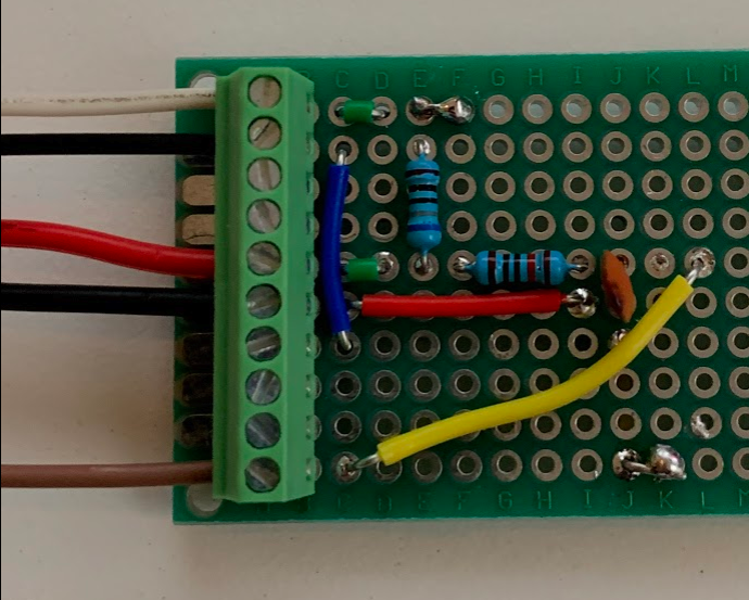
very very VERY crude but this is what I can up with. I'm not good at soldering but this is the board I came up with. The top white is 5V in and black is Ground. The Red and black in the middle is the tank input and the brown output will go to the ADC on the Expander Pi board (port 5 for Tank 1). I did have the VRef on the board replaced from the 4.096v to 1.8v. I had originally planned on doing the entire board for three tanks and two temp, but I will never use the other ports so I didn't bother.

Had the cerboGX been out when I built my pi, I would have just bought that. However I cut out some panels in my van to fit the 7 inch pi screen and the 5 inch Cerbo screen won't fit.


0 Likes 0 ·
1599686610061.png (1.5 MiB)
1599688748647.png (709.9 KiB)
jeroend avatar image jeroend nebulight commented ·

Perhaps a silly question: Why are you not simply changing the vref value to 4.096 in the dbus-adc.conf file?

0 Likes 0 ·
nebulight avatar image nebulight jeroend commented ·

I started this long ago before I even knew about the config file. All the old conversations never mentioned it and always talked about the vref as 1.8 so that’s why it was swapped out. I have another board that has the stock vref that I’ll try out.

0 Likes 0 ·
Rob Duthie avatar image Rob Duthie jeroend commented ·

Tried that did not work very well, as there is in something else in the code that needs changing some were to correct it, just by using the 1.8v ref device solves all the issues and it works OK with no problems and is accurate.

Rob D

NZ

0 Likes 0 ·
trygvelu avatar image trygvelu jeroend commented ·

I have an ADC board with VRef tied to +5V. It works fine with just setting the Vref value in the dbus-adc config file. You just need the correct pull-up (680 ohm) to +5V. The 1.8V Vref will give better resolution on the adc values, but with tank sensors that's not really an issue.

0 Likes 0 ·
jeroend avatar image jeroend trygvelu commented ·

Thanks I will try that first then before making adjustments to the Vref.

0 Likes 0 ·
jeroend avatar image jeroend jeroend commented ·

I messed about quite a bit with the vref but also with the other components needed to make the tank sensors work. Like nebulight I omitted the BAT54S for the tank sensors and that works. (not sure what the BAT54S really improves, the 5V/3.3V on the pi seems stable enough)).

A different story is the temperature input. I just cannot get it to work (neither with 1.8V ref nor 4.096V) I connected it like in the schematic from Rob Duthie and can see a sensor value allright, it is just not displayed in the gui. There it says Reverse Polarity or Disconnected (or Unknown) when not connected at all. I tried a couple different LM335's but unless all 5 are broken or from a bad batch I need to do something else..... but what? Any suggestions?

0 Likes 0 ·
Rob Duthie avatar image Rob Duthie jeroend commented ·

Have you updated the correct files and overlays into boot directory, for the MCP3208 chip set etc?

Regards

Rob D NZ

0 Likes 0 ·
jeroend avatar image jeroend Rob Duthie commented ·

Well I suppose so, since the tank inputs work it certainly looks that way. I can also see the value change and displayed if I read the dbus-adc.

I’ll try to downgrade the dbus-adc tomorrow to a lower version (currently on 1.27) to see if that makes a difference.

0 Likes 0 ·
Rob Duthie avatar image Rob Duthie jeroend commented ·

I do have the copies the files i use with no issues at all for temp and tank readings. It can be slow to react due to having some hysteresis in the software to stop slosh readings.

I am running the latest version 2.60 to date.


Regards

Rob D

NZ

0 Likes 0 ·
jeroend avatar image jeroend Rob Duthie commented ·

It turned out all 5 LM335's I was using were broken or otherwise not fit to be used. I connected the temp sense cable that came with teh Victron Multiplus and that instantly gave a reading. Thanks all for trying to figure this one out. I will source LM335's from another place.

0 Likes 0 ·
Rob Duthie avatar image Rob Duthie jeroend commented ·

The BAT54S are for static protection and over voltage protection.

0 Likes 0 ·
dennis-brok avatar image
dennis-brok answered ·

so its working ? ?


2 |3000

Up to 8 attachments (including images) can be used with a maximum of 190.8 MiB each and 286.6 MiB total.

ghostrider avatar image
ghostrider answered ·

Very cool to see this! I'm getting into a Pi setup now also and am considering the tank measuring tools. The catch for me is that I can't have resistive style senders. The sensors are already installed and wrapped in a outer tank that is insulated for winter use. Would be a HUGE headache just to install a new sensor.

So, I only have what is essentially 3 fluid sensors mounted at different heights in the tank - 1/3, 2/3, FULL..the level is determined by which of the 3 sensors/switches are triggered by fluid.

While it wouldn't be exact, since I only have a resolution of 4 sensors (empty or all off is the 4th option), I would like to try to get the sensors to read in Venus.

Any ideas on how the ADC could read this? While I did do some electrical engineering in college, but then lived a life of software so I've forgotten much. Cant remember how I would wire that. Maybe some form of series so that the voltage fed in matches what is expected as more switches are turned on?

4 comments
2 |3000

Up to 8 attachments (including images) can be used with a maximum of 190.8 MiB each and 286.6 MiB total.

wkirby avatar image wkirby ♦♦ commented ·

If you used a string of three 60Ω resistors in series to make up 180Ω. Then each of your three switches could connect across each resistor and short circuit that resistor when the level comes up o that switch. When all three switches are closed then the string will be 0Ω. Viola, 0-180Ω, although very coarse.
Now, 60Ω resistors are non existent, closest is 60.4Ω in the E96 range which are probably stupidly expensive. You can make up a 60Ω resistance by using two 30Ω resistors from the more common E24 range.

0 Likes 0 ·
Ian Jordan avatar image Ian Jordan commented ·

Sorry if this is a bit late, did you ever try this? We are in exactly the same position with our CBE level sensors so I want to do the same thing. I'm just trying to understand where this resistance network output is then hooked up to?

0 Likes 0 ·
jeroend avatar image jeroend Ian Jordan commented ·

To one of the ADC ports and Ground

0 Likes 0 ·
Rob Duthie avatar image Rob Duthie jeroend commented ·

Hi Schematic of a working raspi HAT with all functions running.

Regarsd
Rob D

NZ

Victron Raspi Hat.pdf

0 Likes 0 ·
victron-raspi-hat.pdf (704.3 KiB)
5teve avatar image
5teve answered ·

@nebulight @Rob Duthie

HI Both - I have copied the work posted above (using the pictures of the breadboard and descriptions), but using a mcp 3008, I muddled my way though the software side.. i have checked double checked and triple checked the wiring on the breadboard, I have tanks and temp sensors appear, however I cannot get a reading that makes any sense

I am using a 240-30 waste gauge (reads correctly with the multimeter) however when I hook it up, empty is showing as 82% and full goes short circuit in the remote console.

Would using the 3008 make a difference with being 10 bit? Could anyone suggest where to look for troubleshooting this. I'm new to this kind of thing so fairly certain its probably me.. however i am failry good at copying stuff :)

Correct resistors are in place. I have a 1.8v ref voltage and vdd of about 4.7v

The 5v nominal feed to the gauge measures about 0.6v after the 680r resistor (hoping thats right!)

Any suggestions would be gratefully received as i want to use something like this (or maybe a modified hat) until The Stetson is available..


Steve

4 comments
2 |3000

Up to 8 attachments (including images) can be used with a maximum of 190.8 MiB each and 286.6 MiB total.

Rob Duthie avatar image Rob Duthie commented ·

Hi

Analog input is setup for the MCP3208 chip which is 12 bit , you need proper Vref chip to get accurate readings, i have used the resistor network in testing and they are poor and depending on the input voltage it swings to much causes errors and bad readings.

Fit a Vref chip and all problems go away.

You have load the correct modified dtb file for the MCP3208 chip set into the Uboot overlays folder?

Victron Raspi Hat.pdf

Regards

Rob D

NZ

0 Likes 0 ·
victron-raspi-hat.pdf (704.3 KiB)
5teve avatar image 5teve Rob Duthie commented ·
@Rob Duthie Thanks...

I can only get the 3008 chip locally to me (im impatient)

I loaded the DTB file for the 3008 and get readings for the analogues in the remote console so assuming thats ok. The DTB file came from a search online..

With regard to accurate.. close would be ok.. but this is all over, the remote console obviously damps the readings.. but when it should be at 0% it sits on 82% so not even close.. if it was swinging around.. then yes i'd understand I need better.. but when its out by this much i'm figuring something else is wrong! Is set up the same as @nebulight shows in his images.. but not giving the same results..

I'm sure just getting a hat would be easier.. i've just gotta find one and then work out how to change the vref on it.. or just buy a cerbo.. haha

Steve

0 Likes 0 ·
Rob Duthie avatar image Rob Duthie 5teve commented ·

Hi

You need the correct dtb file as my file has being modified to suit the 12 bits etc.

The Vref is very important to have stable otherwise the readings are all over the place. I have done the same it was hopeless.

Regards

Rob D

NZ

0 Likes 0 ·
fgs-pantera avatar image fgs-pantera commented ·

@5teve Hi!

I have the same 3008 chip. I'm wondering if you could solve the software side? I have the hardware running but i'm completely lost in setting the pi to work with the pi running venus!

0 Likes 0 ·
adamr100 avatar image
adamr100 answered ·

@nebulightDo you still have a source in the UK who I can purchase one of these boards off?

1 comment
2 |3000

Up to 8 attachments (including images) can be used with a maximum of 190.8 MiB each and 286.6 MiB total.

nebulight avatar image nebulight commented ·

Expander Pi was the hat, but it will take some modification to get working right.

https://www.abelectronics.co.uk/p/50/expander-pi


0 Likes 0 ·
chris-smith avatar image
chris-smith answered ·

So the missing iio directory is not a problem?

2 comments
2 |3000

Up to 8 attachments (including images) can be used with a maximum of 190.8 MiB each and 286.6 MiB total.

Rob Duthie avatar image Rob Duthie commented ·
No
1 Like 1 ·
chris-smith avatar image chris-smith Rob Duthie commented ·
Sorry I voted that down by mistake....
0 Likes 0 ·
Rob Duthie avatar image
Rob Duthie answered ·

Hi Have you added the config file to the Uboot directory.?

dtoverlay=mcp3208:spi0-1-present

2 |3000

Up to 8 attachments (including images) can be used with a maximum of 190.8 MiB each and 286.6 MiB total.

chris-smith avatar image
chris-smith answered ·

I have the :

dtoverlay=anyspi:spi0-0,dev="microchip,mcp3208"

command in /Uboot/config.txt

do I add

dtoverlay=mcp3208:spi0-1-present

to the same file?

I tried it. It didnt make any difference.

The reading on the input to the chip coming from the tank sensor on pin 2 is 0.147 volts (tank empty) 1.188 volts (tank full). I have the 1.8 volt reference chip installed. Do these voltages sound right? I installed the resistors per diagram.

Thanks in advance for any help.

3 comments
2 |3000

Up to 8 attachments (including images) can be used with a maximum of 190.8 MiB each and 286.6 MiB total.

sv-soleil avatar image sv-soleil commented ·

@Rob Duthie @trygvelu


Just to confirm, the config.txt file should end like this;

@Chris Smith I noticed you didn’t end up having the second line?

0 Likes 0 ·
img-7320.jpeg (171.8 KiB)
sv-soleil avatar image sv-soleil commented ·

@Chris Smith I noticed that you only included these lines

1710476278491.png

Why did you exclude this?dtoverlay=anyspi:spi0-0,dev="microchip,mcp3208"

0 Likes 0 ·
1710476278491.png (23.7 KiB)
sv-soleil avatar image sv-soleil commented ·

I find that you don’t need the mcp3208.dbto file at all, and that anyspi.dbto along with dtoverlay=anyspi:spi0-0,dev="microchip,mcp3208" works perfectly.

0 Likes 0 ·
Rob Duthie avatar image
Rob Duthie answered ·

Yes correct, do you have the correct overlay file to suit? named correctly etc?

I have tested and running on Raspi 3 and 4 with no issues to date, and installed on serval sites for clients etc.

1 comment
2 |3000

Up to 8 attachments (including images) can be used with a maximum of 190.8 MiB each and 286.6 MiB total.

sv-soleil avatar image sv-soleil commented ·

@Rob Duthie @trygveluby correct overlay files do you mean these two?


File was obtained from here and renamed .dbto

https://github.com/aaronsb/victronvenussupport/blob/master/mcp3208-overlay.dtb

0 Likes 0 ·
img-7322.jpeg (346.3 KiB)
chris-smith avatar image
chris-smith answered ·

I found I didn't have the MCP3208-overlay.dtbo file in the the overlays directory. So I downloaded it from your github file and renamed it from dtb to dtbo. Still no luck. The "No tanks found" screen is getting me down now....


3 comments
2 |3000

Up to 8 attachments (including images) can be used with a maximum of 190.8 MiB each and 286.6 MiB total.

Rob Duthie avatar image Rob Duthie commented ·
You need the modified one file the one on github or standard one is not being modied yet for all the analog ports.
0 Likes 0 ·
chris-smith avatar image chris-smith Rob Duthie commented ·
Thanks Rob, how do I get hold of the modified file?
0 Likes 0 ·
sv-soleil avatar image sv-soleil chris-smith commented ·

https://github.com/aaronsb/victronvenussupport/blob/master/mcp3208-overlay.dtb


@Chris Smith

So this file won’t work? We need a modified file?? Where can we get that?

0 Likes 0 ·
chris-smith avatar image
chris-smith answered ·

To be clear I need both overlay files installed and both config.txt commands to activate them? Are there any other checks I can make? I have checked all the voltages on the hardware side. I have checked that dbus-adc is running. Maybe my expander pi board is duff?

2 |3000

Up to 8 attachments (including images) can be used with a maximum of 190.8 MiB each and 286.6 MiB total.

chris-smith avatar image
chris-smith answered ·

I am using only pins 2 4 and 6 on the expander pi so my dbus-adc.conf looks like this:

device iio:device0

vref 1.8

scale 4095

tank 2

tank 4

tank 6

I this correct?


3 comments
2 |3000

Up to 8 attachments (including images) can be used with a maximum of 190.8 MiB each and 286.6 MiB total.

Rob Duthie avatar image Rob Duthie commented ·

if you you read all the threads it is there on how to do it.

0 Likes 0 ·
chris-smith avatar image chris-smith Rob Duthie commented ·
Rob,


I have sent you an Email. Hope that is OK.


Chris


0 Likes 0 ·
seekingdave avatar image seekingdave Rob Duthie commented ·
Hi Rob, I know you are likely to be sick to death of this thread but.. I am having some problems getting my head around this. I have a Pi 4B running the 3.20 OS. I have 4 resistor type tank senders already installed into the tanks. I have been going through the thread but can't seem to get it all into my thick head. Is there any way you could send me a link to a github page with all the update software I need to install into the pi and a brief instructions regarding which expander to get and how to modify. I am based in Tauranga and am more than happy to pay for your time to help with this or could come over to Rotorua and see you in person if that would work. Sorry mate, I know how frustrating being asked the same thing over again can be. Hope to hear from you soon. Regards Dave
0 Likes 0 ·
chris-smith avatar image
chris-smith answered ·

Having spent weeks trying to get this to work with a lot of help from Rob Duthie I was finally successful in getting the analog ports to show up on both a Raspi3 and a Raspi 4. I thought I should document exactly what I did in case it helps someone else (no guarantees!) . I have literally documented every tiny step because I did essentially the same things many times in a different sequence and it didnt work. I still cannot get the expander pi board to work and am resorting to a bare mcp 3208 chip and a breadboard:


  • Download Venus OS image and burn to micro SD card
  • While still in windows (or your desktop OS) copy the correct mcp3208.dtbo file (see thread above) to the overlays folder on the micro SD card
  • Edit the config.txt file and add the following lines in the [All] section

dtparam=spi=on

dtoverlay=mcp3208:spi0-1-present

  • Insert the micro SD card in the Raspi and boot up connected to your network by ethernet
  • Find the IP address of the Raspi (I use Victron Connect bluetooth)
  • Open the remote console on your desktop
  • Setup superuser access and password and enable SSH
  • Using Winscp edit the dbus-adc.conf in the etc/venus folder to read as follows:


device iio:device0

vref 1.8

scale 4095


tank 0

tank 1

tank 2

tank 3

temp 4

temp 5

temp 6

temp 7


make sure there is a carriage return at the end of the text. It didn’t work until I added this although it might have been something else that made the critical difference……..


  • Reboot
  • Check for analog ports in the I/O page of settings
  • Continue to setup the system using setup helper addfing Guimods etc. All the tanks and temperatures should show up on the GUI.


2 |3000

Up to 8 attachments (including images) can be used with a maximum of 190.8 MiB each and 286.6 MiB total.

chris-smith avatar image
chris-smith answered ·

On the expander Pi I have connected a 1.8 volt reference chip to the vref pin and desoldered the vref jumper. I have built the correct tank sender circuit per this thread. I have checked all the voltages at the various points and they all seem sensible. Voltage input to the expander Pi analog port increases and decreases from zero to about 1.2 volts as I move the tank float up and down but the Raspi doesn't read anything into the analog ports. I have installed i2C as according to the expander pi instructions this is required. Does anyone who has this working know what else needs to be done? The expander pi manufacturer can only suggest I test it with Raspberry Pi OS.

2 |3000

Up to 8 attachments (including images) can be used with a maximum of 190.8 MiB each and 286.6 MiB total.

zalmon avatar image
zalmon answered ·

Do we have any progress with the system?

Any standard hat that can help us?

4 comments
2 |3000

Up to 8 attachments (including images) can be used with a maximum of 190.8 MiB each and 286.6 MiB total.

Rob Duthie avatar image Rob Duthie commented ·
0 Likes 0 ·
victron-raspi-hat.pdf (737.1 KiB)
zalmon avatar image zalmon Rob Duthie commented ·

Where can I buy it?

0 Likes 0 ·
Rob Duthie avatar image Rob Duthie zalmon commented ·

Have not made it yet others i are given design to have or are doing it.

I have tested prototypes OK.

0 Likes 0 ·
zalmon avatar image zalmon Rob Duthie commented ·

If it is possible to send files for this project for construction?

sjsp1968@gmail.com

0 Likes 0 ·
hoss avatar image
hoss answered ·

Hi Rob, great work. Would it be possible to send me the gerber, sch, bom? I'll knock one up. Thanks - hoss@outlook.com

2 comments
2 |3000

Up to 8 attachments (including images) can be used with a maximum of 190.8 MiB each and 286.6 MiB total.

tcrichton avatar image tcrichton commented ·
Fancy knocking up two? Don't suppose you're in the UK?
0 Likes 0 ·
Rob Duthie avatar image Rob Duthie tcrichton commented ·
NZ
0 Likes 0 ·
jimmyendt avatar image
jimmyendt answered ·

Hello,


I'm looking to connect resistive ( 0 -190 ohm) tank level sensors to my raspberry pi venusos setup. I've searched everywhere, but are still a bit lost in this matter.


As I understand in the comments above you need a ADC converter (analog to digital) a mcp2308 chip sounds like the chip that worked for others users on this great forum.

I also found the awesome HAT Rob Duthie has developed and think that would be an amazing addition to my setup. I'm not technical enough to build it myself and have allready asked where to buy:)


This would seem like a plug and play option right?


my questions:

1. About the volt ref. 1.8 as I understand this is something you can do in the software, but this would make it less accurate, correct?

2. to add the 0 - 190 Ohm tank level senders to the ADC chip, I'm confused. Do you need additional hardware to make it work? Resistors, capacitors?

3. If the answer to 2 is yes, where can I find additional info? ( despite all the information above my mind is still not able to understand it fully)


4. would a HAT like the one below work ? (there is a MCP2308 chip)


https://www.tindie.com/products/cburgess129/high-precision-12-bit-adc-hat-for-raspberry-pi/

this one you can set the Vref to 3.3 of 5. volts?


On that site there is also a simpler version

https://www.tindie.com/products/cburgess129/12-bit8-channel-adc-hat-for-raspberry-pi-v30/ 

2 |3000

Up to 8 attachments (including images) can be used with a maximum of 190.8 MiB each and 286.6 MiB total.

sv-soleil avatar image
sv-soleil answered ·

@trygvelu i have followed your advice above but am getting the following error: cannot open libevent-2.1.so.6 img-7318.jpeg @Rob Duthie this is so confusing, wish there could be one centralized and updated guide somewhere. I hope I found all the correct files.


img-7318.jpeg (482.3 KiB)
5 comments
2 |3000

Up to 8 attachments (including images) can be used with a maximum of 190.8 MiB each and 286.6 MiB total.

trygvelu avatar image trygvelu commented ·
It seems dbus-adc is missing some dependency on the libevent library. What version of Venus are you running?
0 Likes 0 ·
sv-soleil avatar image sv-soleil trygvelu commented ·
@trygvelu @Chris Smith @Rob Duthie


Any chance one of you with a working system could please send me the dbto file? Or post a url to it?

0 Likes 0 ·
Rob Duthie avatar image Rob Duthie commented ·
Follow, read the above blog information to make it work.
0 Likes 0 ·
sv-soleil avatar image sv-soleil Rob Duthie commented ·
Please be more specific as it is not clear what I need to follow?
0 Likes 0 ·
sv-soleil avatar image sv-soleil sv-soleil commented ·
What do you mean by “above blog”? Which comment? There are conflicting suggestions.
0 Likes 0 ·
sv-soleil avatar image
sv-soleil answered ·


This is how I installed dbus-adc

  1. opkg update
  2. opkg install dbus-adc

img-7324.jpeg


img-7324.jpeg (69.8 KiB)
3 comments
2 |3000

Up to 8 attachments (including images) can be used with a maximum of 190.8 MiB each and 286.6 MiB total.

sv-soleil avatar image sv-soleil commented ·

img-7327.jpeg

The error occurs when executing dbus-adc as shown above.

when I ran “opkg update” did overwrite a file with a new version? Solution?

0 Likes 0 ·
img-7327.jpeg (121.0 KiB)
sv-soleil avatar image sv-soleil sv-soleil commented ·

solved this error by creating a symbolic link to the new file:


cd /usr/lib

ln -s libevent-2.1.so.7 libevent-2.1.so.6

ln -s libevent_pthreads-2.1.so.7 libevent_pthreads-2.1.so.6

0 Likes 0 ·
Show more comments
Rob Duthie avatar image
Rob Duthie answered ·

Read the above blog tells you what to do.

No install OPKG required now.

2 |3000

Up to 8 attachments (including images) can be used with a maximum of 190.8 MiB each and 286.6 MiB total.

sv-soleil avatar image
sv-soleil answered ·

The “above blog” is extremely confusing, could you please help by bring more precise? Thanks.


When you say no OPKG required, do you mean this needs to be removed??

kernel-module-mcp320x-5.10.110-rpi-venus-4 - 5.10.110-rpi-venus-4-r0


2 comments
2 |3000

Up to 8 attachments (including images) can be used with a maximum of 190.8 MiB each and 286.6 MiB total.

Rob Duthie avatar image Rob Duthie commented ·

Follow my blob above it will give the answers etc.

(When you say no OPKG required, do you mean this needs to be removed?? this is the old way of doing it)

You will ned the correct MCP3208 overlay file for it to work correctly email me you address then i can send it.

Regards

Rob D

NZ

0 Likes 0 ·
sv-soleil avatar image sv-soleil commented ·

I’ve figured it out. Apparently no need for an updated mcp3208 file. It’s working.

img-7548.jpeg

0 Likes 0 ·
img-7548.jpeg (150.5 KiB)
sv-soleil avatar image
sv-soleil answered ·

@Rob Duthie could you provide a URL to the necessary files or if you can’t do this an email to svsoleil@protonmail.com. Thanks.

FYI, I am pulling the MC3208 overlay currently from here (renamed as a dtbo): https://github.com/aaronsb/victronvenussupport/blob/master/mcp3208-overlay.dtb

2 comments
2 |3000

Up to 8 attachments (including images) can be used with a maximum of 190.8 MiB each and 286.6 MiB total.

sv-soleil avatar image sv-soleil commented ·

This is my most recent error message: veDbusAddRemoteService failed.

img-7524.jpegveDbusAddRemoteService failed

I am basically stuck here and unable to make any progress on this. I’ve spent days struggling. Any advice appreciated?

img-7528.jpeg


0 Likes 0 ·
img-7524.jpeg (283.9 KiB)
sv-soleil avatar image sv-soleil sv-soleil commented ·

Solved!

All these errors were the results of me using outdated dbus-adc files.

DO NOT USE this zip file: https://community.victronenergy.com/storage/attachments/12667-dbus-adc.zip


0 Likes 0 ·
sv-soleil avatar image
sv-soleil answered ·

This is what finally worked for me:


https://community.victronenergy.com/questions/270786/mcp3208-raspberry-pi.html

2 |3000

Up to 8 attachments (including images) can be used with a maximum of 190.8 MiB each and 286.6 MiB total.