question

janvi avatar image
janvi asked

Calculations for th RS450-200

Reading and understating the data sheet of the big RS shows, that the device is composed of input and output circuit. The input circuit has absolute Limit of 450 Volts while the output circuit is limited to 200 Ampere.


Connected to a 48V battery, the maximum output power is 200x48 = 9600 Watt while the datasheet shows a maximum of 11520 Watt. The reason for this diffrence is shown in the maxium voltage for 48V battery what will be calculated from 11520 W / 200 A = 57,6 Volt. This is the same voltage given in datasheet for maximum constant battery voltage.


Further we have to regard the maximum input values in calculations. My panels have a nominal voltage of 41,7V at 10,36 A what makes 432 Watt at the condition of STC illumination what are 1kW/m² at 25 degree celsius.


Unfortunately, the datasheet shows a maximum input voltage of 8x battery float voltage with VOC what is the open circuit voltage of the panel array. As the default float voltage is 57,6 Volt, the maximum string VOC will be 460,8 Volts. This already violates the maximum input voltage of 450 Volt why we only have to take the 8x VOC limitations in account for float voltages smaller than 56,25V.


For the reason of typical high intrinsic resistance, my panel datasheet shows a open circuit voltage of 49,8 Volt max what makes 398,4 Volt for a 8 panel series string. For that voltage, we could lower the floating voltage down to a minimum of 398,4V / 8 = 49,8 Volts. Assume the 450V maximum limit, a series string of 9 panels with 9x49,8=448,2 Volts would be possible.


As far as we not assume a reverse polarity connection, the maximum panel short circuit currents are not taken into account. A string of 8 panels delivers a power of 398,4V x 10,36 A = 4127 Watt. This is already limited by the max 4000W per MPPT of the RS450 datasheet. Connecting the 4 inputs, this gives a input power of 4x4000W = 16000 Watt while the output circuit is limited to 11520 Watt. This would be a loss of aprox 40% or over 4000 Watt of the panel power why we should calculate the usable input power in comparison to the output power rather than the maximum input limits.


Anyhow each switching regulator has a maximum or typical efficieny what I cannot find in the data sheet. Are there any rules of thumb on how much power we have to feed into the RS450 to reach the maximum output power ?


rs450
3 comments
2 |3000

Up to 8 attachments (including images) can be used with a maximum of 190.8 MiB each and 286.6 MiB total.

klim8skeptic avatar image klim8skeptic ♦ commented ·

@Janvi Anyhow each switching regulator has a maximum or typical efficieny what I cannot find in the data sheet.

As per the datasheet the max efficiency is 96%. For the rated 11.5kW output you would need an array larger than 12kW.

4 strings of 8 series 432w panels would give a nominal array output of 13.8kW.

Victron online MPPT calculator. is useful to verify array proposals.

1 Like 1 ·
janvi avatar image janvi klim8skeptic ♦ commented ·

Many thanks for the hint. I did not see the 96% in datasheet. Anyway, this is absolute maximum and conditions therefore unknown. Assume eddy currents, iron and copper losses I doubt and my estimations are about anything typical of 90%. Even a simple passive connection with only 5 mOhms contributes one full Watt of losses at 200 Amp why I hardly believe the 96% are practically reachable. On the other hand, 90% efficiency needs to dissipate 1kW of heat why the device requires a noisy fan with certain distance to its neigbours. Probably the only way is to use my clamp-on ammeter to see on how the RS450 is really performing.

0 Likes 0 ·
klim8skeptic avatar image klim8skeptic ♦ janvi commented ·

@Janvi I hardly believe the 96% are practically reachable.

96%+ efficiency has been achievable in grid tied PV inverters, depending on design topology for yonks.

Transformerless (TL) designs, where the array DC is switched across the AC. Image from Power One PVI-4.2-OUT inverter circa 2010. Max eff of 96.8%

eff-pvi-42-out-tl.png

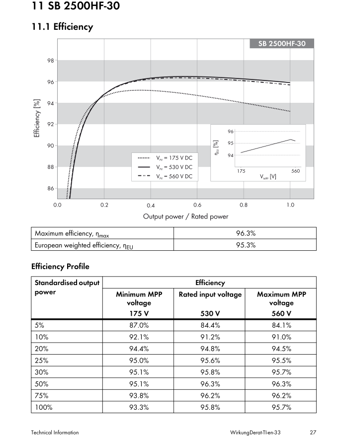
High Frequency (HF) designs use a small toroid isolation transformer between the array DC and AC output. Image from SMA SB 2500HF circa 2010. Max eff of 96.3%.

eff-sb-2500hf.png

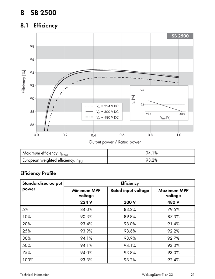
Low Frequency (LF) designs use (somewhat) conventional iron core transformers between the array DC and AC output. Image from SMA SB2500 circa 2005. Max eff of 94.1%.eff-sb2500-lf.png

Efficiency is dependent on 3 main things. Input voltage, output voltage and output power. Temperature might also have an effect.

While the examples shown are Grid Tied Inverters, DC-DC mppt's will be similar.

1 Like 1 ·
eff-pvi-42-out-tl.png (287.1 KiB)
2 Answers
Alexandra avatar image
Alexandra answered ·
@Janvi

Consider all of the above factors, and your local install conditions.

In summary, your voc x 8 (max, but with in the 450v at min temperature in mind)

The absolute max input amps of 30v per tracker. As long as you don't make a mistake, otherwise keep in kind the max short circuit current.

With all the different factors, low irradiance areas benefit from being able to 'over panel'.

Or allow you to overpanel for bad solar months, if you have alot of difference in seasonal yeilds.

2 |3000

Up to 8 attachments (including images) can be used with a maximum of 190.8 MiB each and 286.6 MiB total.

janvi avatar image
janvi answered ·

There is no question about the benefit of an over-panelized installation but without figures for efficiency we cannot calculate on how much it is overpanelized. Further there is limited panel space for offshore applications why some users prefere over-mppt´d installations (what would be also a benefit for Victron as the mppt manufacturer)

2 comments
2 |3000

Up to 8 attachments (including images) can be used with a maximum of 190.8 MiB each and 286.6 MiB total.

Alexandra avatar image Alexandra ♦ commented ·
@Janvi

Are you referring to conversion efficiency? Dc to dc?

Its own internal efficiency?

0 Likes 0 ·
Show more comments

Related Resources

Additional resources still need to be added for this topic