question

bradley-thompson avatar image
bradley-thompson asked

Using Smart Shunt as DC Load meter - VRM is not mapping correctly

Hello,

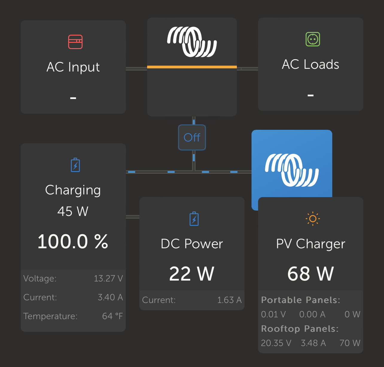
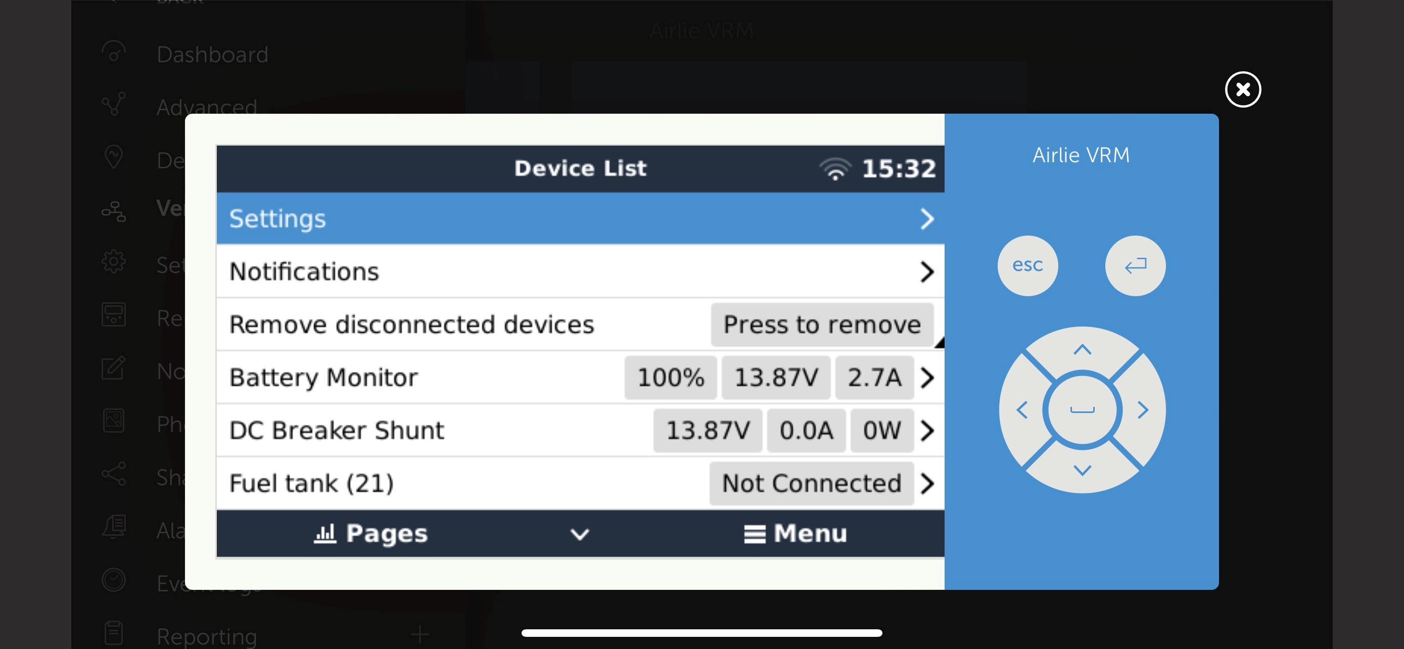
I have setup a Smart Shunt as a DC Load meter in my RV setup. I basically want the Smart Shunt to report the current being used by the DC loads in the RV so that the MPPTs can compensate for it when they are charging the batteries. However, it doesn't seem to be working/reporting correctly. For instance, when I turn on DC loads (lights in this case), the amperage is reported in VRM as going to the general system, not DC loads (note in last picture that the DC meter reads 0.0 amps being used but 22-28w seem to be outflowing constantly). Is VRM working correctly?

Some details:

* Smart Shunt is configured as DC Meter (currently specified as General Loads in misc. settings)

* I'm using DVCC - SVS, SCS enabled.

* I have no way of tracking current in AC loads/sources in the VRM system - I'm looking to add at least another Smart Shunt on my inverter if I can get this working correctly.

* I have the "Has DC System" setting enabled in my GX unit (a Raspberry Pi running VenusOS Large in my case).

* I can see the DC System in the main VRM screen.

System configuration:
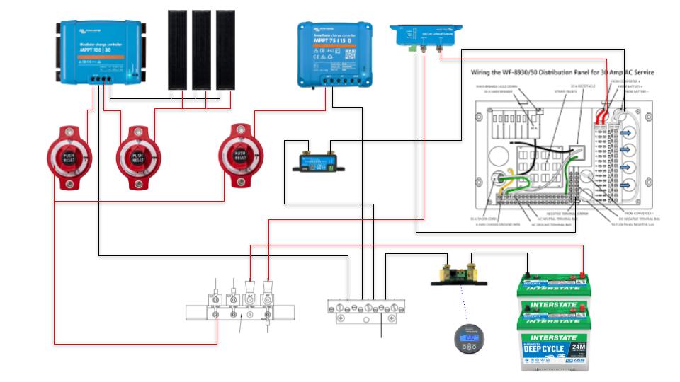
airlie-install.jpg

airlie-vrm.png

dvcc-settings.jpg

vrm.jpg

SmartShuntdc system
airlie-install.jpg (60.4 KiB)
airlie-vrm.png (158.1 KiB)
dvcc-settings.jpg (229.1 KiB)
vrm.jpg (234.3 KiB)
8 comments
2 |3000

Up to 8 attachments (including images) can be used with a maximum of 190.8 MiB each and 286.6 MiB total.

bostonmarinervelectrical avatar image bostonmarinervelectrical commented ·
Looks ok to me. You batteries are being charged (from solar) at 3.4amps so that value shows positive in the battery box. You are outputting 1.63amps to the dc system (also positive). If you were drawing more amps than you were producing, your battery would show a negative amp value.


Both boxes are setup to show amps in to the box = positive. You will always have some current flow to power the system.

Someone correct me if im wrong.

0 Likes 0 ·
Show more comments
pwfarnell avatar image pwfarnell commented ·
Have you got the connections on the shunt the right way round.


Is the shunt measuring all the DC loads, if so you could set it as the "DC system" rather than general loads then the Smartshunt will populate the DC system box. Ignore this if you have other DC loads.

0 Likes 0 ·
Show more comments
2 Answers
bradley-thompson avatar image
bradley-thompson answered ·

Well, I figured it out. I noticed that none of the negatives from the loads were feeding back into the 12v DC panel. Turns out there are three (or more) wiring harnesses that feed into the negative bus that are otherwise unlabeled. I moved some leads around and moved the battery connection to the DC shunt and everything works now as expected. Updating my drawing for anyone else who might be trying to wire this into a WFCO box.

airlie-install-1.jpg


2 |3000

Up to 8 attachments (including images) can be used with a maximum of 190.8 MiB each and 286.6 MiB total.

michaeld avatar image
michaeld answered ·

If you have "has DC system" selected but no shunts configured as "DC system", the DC box will be calculated as the difference between what the inverter is using, what the MPPT is generating and what the battery sees. So if you have any shunts set to "generic load", "DC source", "DC load" etc these will be ignored and it will show the estimate.

If you have one or more shunts configured as "DC system", the DC box will be the sum of those shunts only - it will not estimate as above. So you should only set a shunt as "DC system" if there's absolutely nothing else (excluding inverters and MPPTs) that's bypassing that shunt. Perhaps there's a chassis ground somewhere?

2 |3000

Up to 8 attachments (including images) can be used with a maximum of 190.8 MiB each and 286.6 MiB total.

Related Resources