** Edit **
This version is replaced by the new repo RemoteGPIO, now much easier to install with SetpHelper Package Manager.
All the details of this new version is here:
https://community.victronenergy.com/questions/245584/remotegpio-ex-venus-rgpio-now-available-with-setup.html
Well, this is not a question here, but a solution I built for having additional Relays and Digital Inputs on the Cerbo GX, using the a USB port.
As I wanted the relays to not rely on an external Ethernet network, I went with a Modbus/RTU based relai from Dingtian.
This box provide 8x relays, that can be controlled with Modbus Serial, but also over IP and with various additional protocols: https://fr.aliexpress.com/item/4000999069820.html They have variants of 4 or 8 relays.
A USB to RS 485 adapter will be required. I selected this one as this is coming with a USB cable and can fit nicely on the Cerbo GX: https://fr.aliexpress.com/item/1005004778767986.html
Now we need to do few tweaks so the 4x first relays are completely managed by the Cerbo GX GUI.
Only 4x relays can be added at bus level so the Victron’s Node-Red flow and Cerbo GX Gui can control it.
The remaining relays will be managed directly from Node-Red Modbus flow
I tried to make something as reliable as possible and so far I'm quite happy with the stability. But any suggestions and improvements are welcome!
The below steps requires to ssh to the Cerbo GX with root access.
I suggest you download the configuration files in /data/rgpio so it remains there even after SW upgrades.
Any suggestion to execute the below steps in a better appropriate way (may be also adding automatic adding it from /etc/rcS.d) are welcome.
Repository is here:
https://github.com/Lucifer06/Venus_rgpio
cd /data/
wget github.com/Lucifer06/Venus_rgpio/releases/download/Latest/rgpio.tar.gz
tar -xvzf rgpio.tar.gz
rm rgpio.tar.gz
0/ Configuration of the Dingtian IOT Relay module
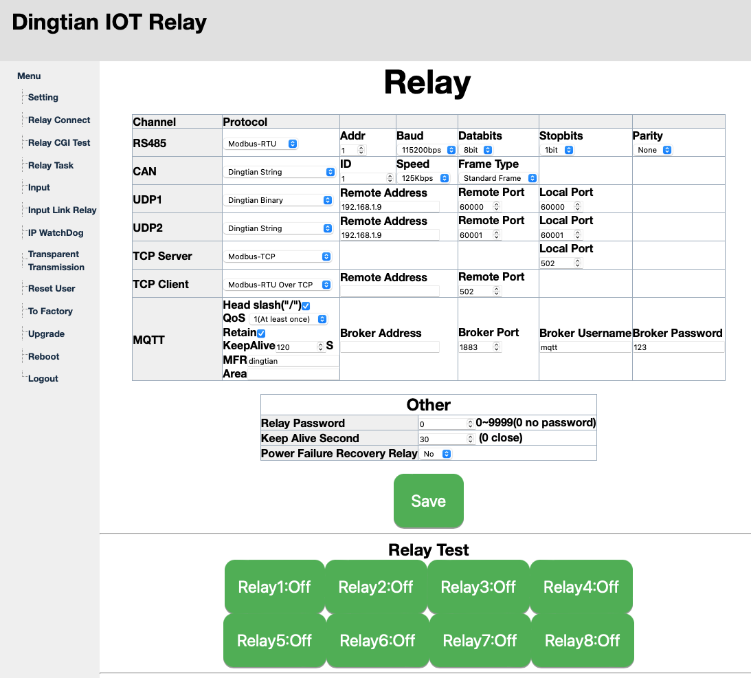
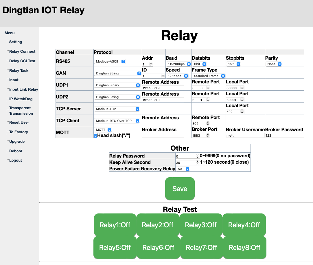
Connect the ethernet interface of the module and access to its configuration page (192.168.1.100 and admin/admin by default).
Configure the RS485 with Protocol Modbus-RTU and set address to 1 (for the first unit).

1/ Creating /dev/gpio links at boot so the bus services are automatically created
ln -s /data/rgpio/conf/S90rgpio_pins.sh /etc/rcS.d/S90rgpio_pins.sh
2/ Modify Relaystate Python script
mv /opt/victronenergy/dbus-systemcalc-py/delegates/relaystate.py /opt/victronenergy/dbus-systemcalc-py/delegates/relaystate.py.ori
cp /data/rgpio/conf/relaystate.py /opt/victronenergy/dbus-systemcalc-py/delegates/relaystate.py
3/ Need to add Relays 3, 4, 5 and 6 in /etc/venus/gpio_list so they can be configured on the GUI
mv /etc/venus/gpio_list /etc/venus/gpio_list.ori
cp /data/rgpio/conf/gpio_list /etc/venus/gpio_list
4/ Need to update Node-Red service for adding the 4x relays
mv /usr/lib/node_modules/@victronenergy/node-red-contrib-victron/src/services/services.json /usr/lib/node_modules/@victronenergy/node-red-contrib-victron/src/services/services.json.ori
cp /data/rgpio/conf/services.json /usr/lib/node_modules/@victronenergy/node-red-contrib-victron/src/services/services.json
5/ Reboot or restart the services
svc -d /service/dbus-systemcalc-py/ ; svc -u /service/dbus-systemcalc-py/
svc -d /service/gui ; svc -u /service/gui
svc -d /service/node-red-venus
6/ Make serial-starter to ignore the USB-RS485 interface
identify ID_MODEL of the interface
udevadm info --query=property --name=/dev/ttyUSB0
With CH341 chipset, ID_VENDOR is USB_Serial
As they don’t put any unique serial number there is an issue when multiple Serial interfaces are using the same CH341 chipset.
This is the case for example with the USB interface to connect the DALI BMS.
Unfortunately I haven’t found a way to program a serial number, so the solution is to track the position of the RGPIO interface:
Always connect the USB-RS485 interface to the first USB interface.
Add the following lines to /etc/udev/rules.d/serial-starter.rules
#Serial-starter to ignore the USB-RS485 (ID_MODEL=USB_Serial) so USB interface for RGPIO works
#ACTION=="add", ENV{ID_BUS}=="usb", ENV{ID_MODEL}=="USB_Serial", ENV{VE_SERVICE}="ignore"
#Serial-starter to ignore the USB-RS485 converter attached to the first USB port so USB interface for RGPIO works
ACTION=="add", ENV{ID_BUS}=="usb", ENV{ID_PATH_TAG}=="platform-1c14400_usb-usb-0_1_1_0", ENV{VE_SERVICE}="ignore"
#
Alternatively, run
/opt/victronenergy/serial-starter/stop-tty.sh ttyUSB0
7 Reboot the RGPIO device and start Node-Red
svc -u /service/node-red-venus
8/ Display and configure the additional 4x relais in the Venus GUI
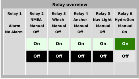
Name and display the additional relays from Settings / Relays in the GUI.
You can swipe to a specific page with the 6x relays, but I believe this is provided by the excellent GuiMods add-on from Kwinderm.

9/ Test with command lines
List of all dbus relays and their status:
dbus -y com.victronenergy.system /Relay GetValue
For some reasons I can’t control the relays. If someone knows the correct command line?
Here is what I tried:
dbus -y com.victronenergy.system /Relay/3/State SetValue 1
Lecture registre nombre de Relais:
/data/rgpio/modpoll/arm-linux-gnueabihf/modpoll -m rtu -b 115200 -p none -d 8 -1 -r 1 -s 1 -c 1 /dev/ttyUSB0
Lecture en continu Digital Inputs:
/data/rgpio/modpoll/arm-linux-gnueabihf/modpoll -m rtu -b 115200 -p none -d 8 -r 11 -s 1 -c 1 /dev/ttyUSB0
Lecture en continu Relais:
/data/rgpio/modpoll/arm-linux-gnueabihf/modpoll -m rtu -b 115200 -p none -d 8 -r 2 -s 1 -c 1 /dev/ttyUSB0
Ecriture registre Relai1 = On:
/data/rgpio/modpoll/arm-linux-gnueabihf/modpoll -m rtu -b 115200 -p none -d 8 -1 -r 3 -s 1 -c 1 /dev/ttyUSB0 257
Ecriture registre Relai1 = Off:
/data/rgpio/modpoll/arm-linux-gnueabihf/modpoll -m rtu -b 115200 -p none -d 8 -1 -r 3 -s 1 -c 1 /dev/ttyUSB0 256
10/ Using Node-Red for controlling the 8x additional relays
The Relays 3, 4, 5 and 6 are normally controlled with Victron’s Relay Nodes, and their status are correctly reported on the Victron GUI
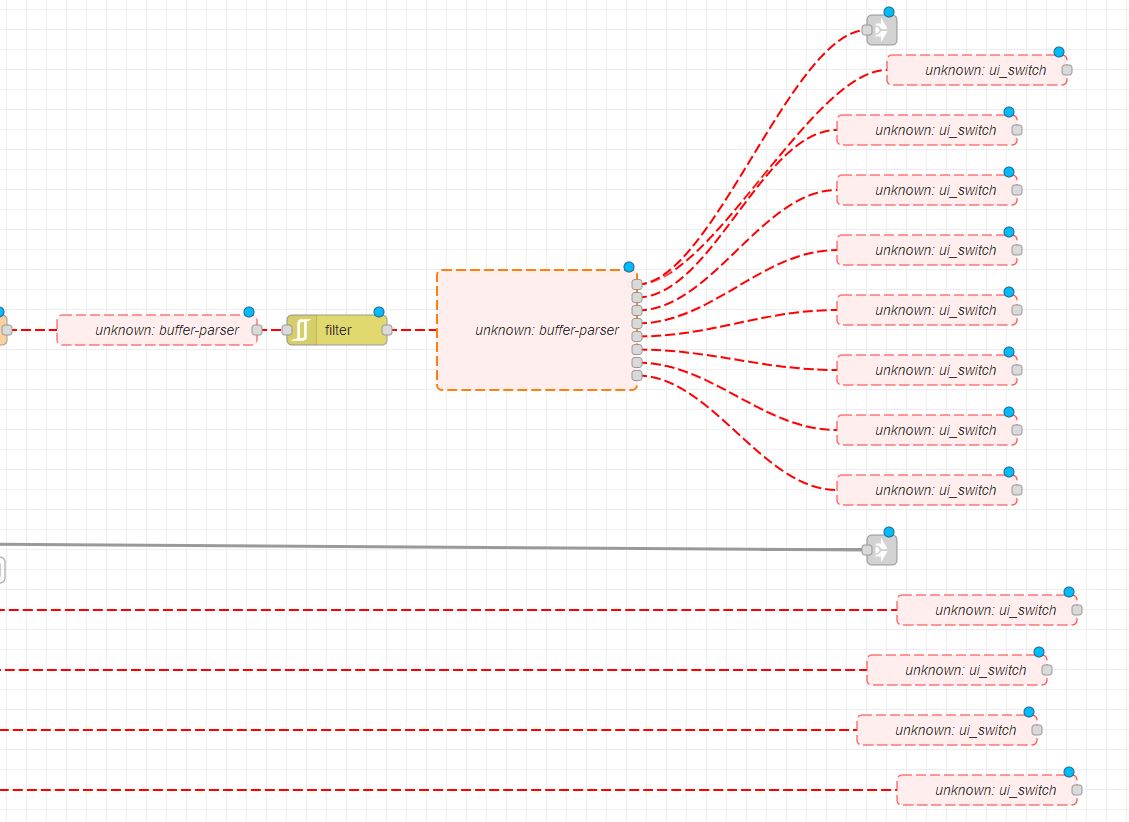
Use flow "Remote Relays 1-8 (RTU).json" as example
The additional 4x relais 7, 8, 9 and 10 are exposed only through Node-Red Dashboard.
They all require the flow Dingtian_Relays.json for sensing the status and controlling the remote Relay from the Dingtian box, attached via RS422 (ModBus RTU protocol).
11/ Additional Digital Inputs
The Dingtian relay box also offer additional Digital inputs.
Here is the flow for sensing the values of the Digital Inputs
**********************************************************************


