question

Sten avatar image
Sten asked

Spreed sheet for calculating CVL on REC BMS

I have made this spreed sheet to calculate CVL voltages on REC BMS.

The hysterese factor in the formula for the CVL calculation is 0.5 on my ABMS. This factor is not configurable. Be avare of that. I made it changable in the sheet to se what it could be with different value, because the 0.5 value does not work very well for me.

CVL calculation


I would have uploadet the sheed but google sheet files is not supportet.

cerbo gxBMS
1 comment
2 |3000

Up to 8 attachments (including images) can be used with a maximum of 190.8 MiB each and 286.6 MiB total.

kevgermany avatar image kevgermany ♦♦ commented ·
@Sten

Moved to modifications space.


0 Likes 0 ·
3 Answers
johanndo avatar image
johanndo answered ·


img-20220722-084408.jpg

I don't know what you are talking about, what is CVL? The user manual says ( - 0.5 x hysteresis ) for charging voltage, what is the middle point between the stop charge and restart charge point based on the chosen hysteresis CHIS and CHAR voltage parameter, of course the middle is always 0.5 (50%), you can set the hysteresis, it is configurable.

This is the charge profile according of the manual for REC ABMS - VICTRON CAN Edition.


1 comment
2 |3000

Up to 8 attachments (including images) can be used with a maximum of 190.8 MiB each and 286.6 MiB total.

Sten avatar image Sten commented ·

CVL is the Charging Voltage Level set in your GX device from REC BMS.

I was not talking about the CHIS parameter as not configurable but the FACTOR 0.5.

With a CHAR = 3.5 (bulk CVL = 14.1V) and CHIS = 0.25V (float CVL = 13.5) you wil have a restart bulk voltage at 12.96V. Way to low in my opinion. I think the FACTOR should be configurable.

I have the manual from REC BMS

https://www.rec-bms.com/wp-content/uploads/2022/02/UserManual_ABMS_Victron_Wakespeed.pdf

Where do you have yours from?

0 Likes 0 ·
johanndo avatar image
johanndo answered ·

You don't understand the meaning of hysteresis. This defines the restart voltage

(CHAR-CHIS). Reduce the hysteresis and it will restart earlier. If you set CHIS to 100mV (0.1) you will charge to 14.6V (3.650V) and restart at 14.2V (3.550V). The second hysteresis is the SOCH that prevents restart like 0.05 would be 5% or in other words wait until SOC drops below 95%.

As the voltage is calculated on the fly, REC choose to smoothe the switching by reducing current by reducing the voltage earlier when approaching the cut off, this is this complicated formula you stumbled upon.

4 comments
2 |3000

Up to 8 attachments (including images) can be used with a maximum of 190.8 MiB each and 286.6 MiB total.

Sten avatar image Sten commented ·

I do understand the hysteresis. In your example the float voltage will be 14.4V!

That would be a very high and bad for lifepo4 battery. 4*(CHAR-(CHIS*0.5))

If I want a charge voltage at 14.1V and a float voltage at 13.5V I will have as I wrote a restart voltage at 12.96V. That is so low that I have to 1. Shortly have a load that can drag the voltage down under that or 2. wait until the battery discharge to the voltage.

Then the higher CVL will kick in. I do now that the SOC hysteresis also have to go under for example 95%.

In a solar system that will almost never happen. As I remember victron has rebulk voltage at 0.1V in there lithium charge profile.

In my example calculation it is 0.5V witch is a big step on lifepo4 system.


I have observed those number in real life on my system, The big hurdle here is the FACTOR

witch should be user configurable in my opinion.

To my nowledge there is a special firmware from REC BMS with a factor at 1, I have wrote an email to REC BMS but have not yet got an answer.

0 Likes 0 ·
Sten avatar image Sten Sten commented ·

For reference I found a post where another user here in forum have the exact same problem as I have. He have aperantly got the special firmware where the 0.5 factor is changed to 1.

https://community.victronenergy.com/questions/109699/rec-bms-cerbo-gx-multiplus-ii-absorption-and-bulk.html

0 Likes 0 ·
johanndo avatar image johanndo Sten commented ·
I see, this are all DVCC related issues.


I use the REC as a BMS and let the chargers manage the normal charging by setting Absorption and Float directly, without this fancy math. The charge disable / re-enable is done by the optocoupler in my system, this only happens if there are imbalances and the absorption point is not reached to stop the charging. Usually doesnt happen, as my charger go to float before the BMS engages and stops them. I use the setting only to allow balancing by protecting the high cell.


Different setup.

0 Likes 0 ·
Show more comments
Sten avatar image
Sten answered ·
Hi
I got an answer from Tine at REC BMS with a new firmware attaced.
Now I have the oportunity to change hysterese factor as needed.
The spreed sheet can still be used to calculate CVL voltages.
****************************************************************************************
Dear Mr. Steen

Excuse me for the long reply.

Attached please find the 2.8 update with CFVC coefficient that can go from 0.1 to 1.0.

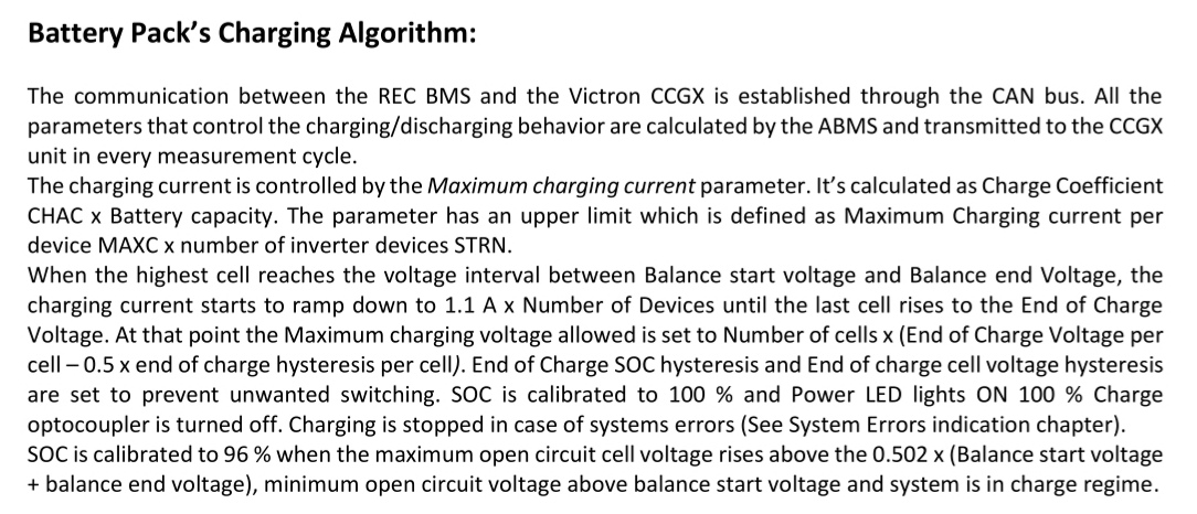
Battery Pack’s Charging Algorithm:

The communication between the REC BMS and the Victron GX device is established through the CAN bus. All the parameters that control the charging/discharging behavior are calculated by the BMS and transmitted to the GX device in each measurement cycle.

The charging current is controlled by the Maximum charging current parameter sent to the GX device. It’s calculated as Charge Coefficient CHAC x Battery capacity CAPA. The parameter has an upper limit which is defined as Maximum Charging Current per Device MAXC x Number of Inverter/Charger Devices SISN. Lowest value is selected:

Table 9: Maximum charging current calculation.

SETTING

VALUE

UNIT

Battery Capacity (CAPA)

100

Ah

Charge Coefficient (CHAC)

0.6

1/h

Maximum Charging Current per Device (MAXC)

75

A

Number of Inverter/Charger Devices (SISN)

2

n.a.

Charge Coefficient CHAC x Battery Capacity CAPA = 0.6 1/h x 100Ah = 60 A

Maximum Charging current per device MAXC x Number of Inverter/Charger devices SISN = 75 A x 2 = 150 A

Maximum charging current is set to 60 A due to lower value of the Charge Coefficient CHAC x Battery Capacity CAPA.

When the highest cell reaches the End of charge CHAR voltage setting, charging current starts to ramp down to 1.1 A x Number of Inverter/Charger Devices SISN until the last cell rises near the End of Charge Voltage CHAR (CC/CV). At that point the Maximum charging voltage allowed is set to Number of cells x (End of Charge Voltage per cell CHAR– Maximum Cell Float Voltage Coefficient CFVC x End of charge hysteresis per cell). End of Charge SOC hysteresis SOCH and End of charge cell voltage hysteresis CHIS is set to prevent unwanted switching. SOC is calibrated to 100 % and Power LED lights ON 100 % Charge optocoupler is turned off. Maximum allowed charging current is set to 50% to allow supplying DC loads from charging devices like MPPTs. Charging current is limited to 30 % of the maximum charging current, but more than 5 A near both ends of temperature (Max cell temperature TMAX and Min temperature for charging TMIN) and when the battery is empty (Max discharging current is set to zero).

Charging is stopped in case of systems errors (See System Errors indication chapter). SOC is calibrated to 96 % when the maximum open circuit cell voltage rises above the 0.502 x (Balance start voltage BMIN + End of charge voltage CHAR), minimum open circuit voltage above balance start voltage and system is in charge regime.

In case BMS is not able to control the MPPT/Non-Victron charging sources directly (MPPT should be set to charge when the remote is in short), a small signal relay can be used to amplify the signal. MPPT should be programmed with its own charging curve set as End of charge voltage x number of cells. Digital output may be programmed with another task on request e.g. heater, under-voltage alarm, …

image.png

Figure 14: Charging diagram.


Maximum Cell Float Voltage Coefficient (CFVC):

Maximum Cell Float Voltage Coefficient CFVC has been introduced into the charging algorithm to enable cell float voltage change after the full charge. It may be set from 0.1 to 1.0 of the End of Charge Hysteresis CHIS. When End of Charge Hysteresis CHIS and End of Charge SOC hysteresis SOCH have been met, full charge is enabled again. @ CFVC 50 % of maximum charging current is allowed to supply DC loads from MPPTs directly without discharging the battery pack below End of Charge Hysteresis CHIS and End of Charge SOC hysteresis SOCH.

Battery Pack’s Discharging Algorithm:

Calculated maximum discharging current is sent to the GX device by CAN communication in each measurement cycle. When the BMS starts/recovers from the error or from Discharging SOC hysteresis, maximum allowed discharging current is set. It is calculated as Discharge Coefficient DCHC x Battery Capacity CAPA. If this value is higher than Maximum Discharging Current per device MAXD x Number of Inverter/Charger Devices SISN, maximum discharging current is decreased to this value.

Table 10: Maximum discharging current calculation.

SETTING

VALUE

UNIT

Battery Capacity (CAPA)

100

Ah

Discharge Coefficient (DCHC)

1.5

1/h

Maximum Discharging Current per Device (MAXC)

100

A

Number of Inverter/Charger Devices (SISN)

2

n.a.

Discharge Coefficient DCHC x Battery Capacity CAPA = 1.5 1/h x 100Ah = 150 A

Maximum Discharging Current per device MAXC x Number of Inverter/Charger devices SISN = 100 A x 2 = 200 A

Maximum discharging current is set to 150 A.

When the lowest cell open circuit voltage is discharged bellow the set threshold CLOW maximum discharging current starts to decrease down to 0.02 C (2 % of Capacity CAPA in A). After decreasing down, maximum allowed discharging current is set to 0 A. SOC is reset to 3 % and Discharging SOC hysteresis is set to 5 %. If the cell discharges below Minimum Cell voltage CMIN, BMS signals Error 2 and SOC is reset to 1 % and internal relay switches off. If the Charger/inverter is connected to the grid maximum allowed discharge current is drawn from the grid. Otherwise, 100 % load current is drawn from the battery until maximum allowed discharging current is set to 0 A. Discharging current is also limited near both ends of temperature (Max cell temperature TMAX and Min temperature for charging TMIN) to 30%, but more than 5 A. If the minimum cell discharges under the Cell-under voltage protection switch-off CMIN x 0.95 for more than 30 s BMS goes to deep sleep mode to protect the cells from over-discharging. OFF-ON switch sequence wakes the BMS from this state. CLOW cell voltage setting should be set to the voltage that corresponds to 3 % of the usable capacity.

image.png

Figure 15: Discharging diagram.

Z lepimi pozdravi / Best regards,
dr. Tine Andrejasic, Ph.D.


--
REC d.o.o.

Novi trg 9

6230 Postojna

Slovenia

SI38163209

-----------------------------------

tel.: +386 (0)5 620 2447

web: www.rec-bms.com


2 comments
2 |3000

Up to 8 attachments (including images) can be used with a maximum of 190.8 MiB each and 286.6 MiB total.

benm avatar image benm commented ·

Hello Sten,

Iam the person that give you the initial setup for this Calculation sheet.

Yours looks a bit nicer, because only the info you really need is in it.


But one thing is new in your sheet.

From where you have the info, that the ""calculated value"" is different as the ""show value"" in the GX?

Is the GX or REC is do this rounding?

Do you know or the connected devices, use the rounded or calculated values?


Ben


0 Likes 0 ·
Sten avatar image Sten benm commented ·

As far as I know, it is the REC bms who is controlling charging and discharging in the system, so it is the values in the REC bms that counts. The values seen in the GX is more for information.

The values in the sheet is information parly from wakespeed and partly from seen when playing around with different values.

Edit: it is Goodmarine not wakespeed i have the information from.

0 Likes 0 ·