question

2hulls avatar image
2hulls asked

Controlling allow-to-charge VE.Bus BMS to Smart MPPT

What is the correct way to communicate allow-to-charge from a VE.Bus BMS to a Smart MPPT?

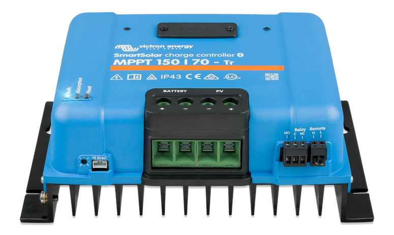
On my sailing catamaran I have Victron Smart LiFePO4 batts, VE.Bus BMS, 150/70 Smart MPPT, 712 BMV (among other components) installed DIY in 2018. Currently not cruising this winter where it's always warm, so first time I've had to deal with LiFePO4 low temperature cutout.

When installing my system, my dealer insisted I needed to use a battery protect between the MPPT output and batteries for overcharge protection. The MPPT Remote on-off terminal is not being used - the two connections are jumpered together to allow the unit to turn on. I do not have battery temp sensors other than the internal ones in the batteries and do not have GX or VE.Direct. I have VE.Smart networking enabled in Victron Connect between the BMV and MPPT, but this does not communicate battery temperature.

When battery temp decreases < 5C, apparently the BMS drops the allow-to-charge voltage as intended, which opens the BP, disconnecting the MPPT from the batteries. This has only happened at night so far, so the MPPT is off anyway. When the batteries have warmed up and the sun is out, charging does not resume, even though the low battery temp condition has cleared, because Error #38 has occurred in the MPPT ("Input shutdown due to battery over voltage"). I do not know if this occurs when the BP opens or when the MPPT turns back on in daylight - possibly causing a voltage overshoot - but it may not matter. The Error #38 is easy to resolve, but inconvenient.

One of the published potential reasons for MPPT Error #38 is: "The battery is disconnected using a Lithium charge relay connected to the “allow-to-charge” output of a BMS. Consider wiring this signal to the Remote terminal of the charger instead. This shuts down the charger gracefully without creating a voltage overshoot."

This sounds like the fix.

It would be easy for me to eliminate the BP and connect the BMS allow-to-charge to the MPPT Remote on-off. Seems to make no difference whether the allow-to-charge has been denied by the BMS due to low battery temp or overcharge. Is this all I need to do? Before trying this I'd like some confirmation that this is a proper change, given the dealer's original insistence to use the BP. At the time I wasn't smart enough to question why not to use the Remote on-off terminal on the MPPT.

Thanks, Dave


MPPT SmartSolarBMSBattery Protect
2 |3000

Up to 8 attachments (including images) can be used with a maximum of 190.8 MiB each and 286.6 MiB total.

6 Answers
nebulight avatar image
nebulight answered ·

Since you have a 150/70 with the remote on/off terminal, then yes you can remove the battery protect and wire the allow to charge direction to the H pin on the 150/70.

A battery protect is often used in installations where you have a smaller mppt without an on/off and a GX device, so the ve.direct port is in use with the GX and you can't use the ve.direct on off cable. However since you don't have either problem, just wire up the allow to charge directly to the H port.

2 |3000

Up to 8 attachments (including images) can be used with a maximum of 190.8 MiB each and 286.6 MiB total.

2hulls avatar image
2hulls answered ·

Thanks, nebulight!

2 |3000

Up to 8 attachments (including images) can be used with a maximum of 190.8 MiB each and 286.6 MiB total.

2hulls avatar image
2hulls answered ·

OK, that didn't work...

I bypassed - eliminated - the battery protect and wired the very same allow-to-charge wire from the BMS that used to be connected to the BP to the right hand + terminal of the Remote on-off on the MPPT - exactly as described in the manual. The MPPT would not turn on. It had power as indicated by the local SmartSolar Control display and the Bulk Charge light was on. But no charging.

I reconnected the BP and reconnected the ATC from the BMS to the BP and re-jumpered the two MPPT Remote on-off terminals. The MPPT turned on as normal and began charging.

There must be something else? Is there an MPPT setting that needs to be changed? I assume the Remote on-off + (right hand side) terminal is the same as the H port in nebulight's answer, above. Is this incorrect?

Dave

2 |3000

Up to 8 attachments (including images) can be used with a maximum of 190.8 MiB each and 286.6 MiB total.

nebulight avatar image
nebulight answered ·

Is this your model? It should be labeled H (the right most terminal and the left port). Here is a mention in the manual:
3.11. Remote on/off
The solar charger is equipped with a remote on/off terminal. The solar charger can be turned on or off remotely by connecting a
switch to this terminal or by presenting a high signal to the H terminal or a low signal to the L terminal. Alternatively this terminal
can be connected to an external control device, for example a lithium battery management system (BMS).
There a several ways to turn the solar charger on using the remote terminal(s):
• The L and H terminals are interconnected connected via a switch or relay.
When the voltage on the H terminal is more than 2.9V (up to the battery voltage) via a switch, relay or other external device,
like a battery BMS.
• When the voltage on the L terminal is pulled to battery minus. (<3.5V) via a switch, relay or other external device, like a battery
BMS.
A virtual remote on/off terminal can be created by using the VE.Direct non inverting remote on/off cable.
The functionality can be programmed using the VictronConnect App RX port function settings.

2 |3000

Up to 8 attachments (including images) can be used with a maximum of 190.8 MiB each and 286.6 MiB total.

2hulls avatar image
2hulls answered ·

Thanks again, nebulight -

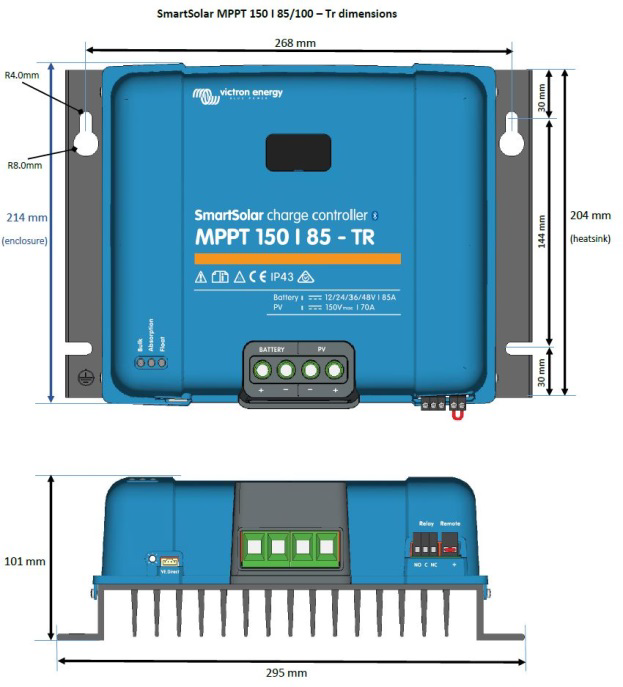
That image is not in my manual, version 01 dated Feb 12th 2018.

This image is in my manual and depicts my MPPT, although not the same model. My 150/70 vs shown 150/85. All else identical.

1640727738429.png

It's hard to see, but the furthest right terminals on the bottom are labeled Remote. The right hand side is also labeled +. The left side has no label. There is no L or H. There has always been the short jumper wire connecting the two sides.

The manual text is as follows:

3.5 Remote on-off

The left terminal is connected to the internal 3,3V supply, with a resistor in

series for short circuit protection.

The right terminal (marked as +) will switch the controller on if >3V is

applied, and will switch the controller off if <2V is applied or if the terminal

is left free floating.

The recommended use of the remote on-off is:

a. A switch wired between the left and right terminal

b. A switch wired between battery plus and the right terminal.

c) A switch between the right terminal and the charge disconnect terminal of a VE.Bus

BMS

Clearly, my component is very different than your image. This difference has to be the root of my problem.

Dave


1640727738429.png (253.8 KiB)
12 comments
2 |3000

Up to 8 attachments (including images) can be used with a maximum of 190.8 MiB each and 286.6 MiB total.

nebulight avatar image nebulight commented ·

I think that may be a typo in the manual as I ran into this before. I'm 99% sure that the H port is on the left with these 150v units. You should be able to use a multimeter to see.

0 Likes 0 ·
2hulls avatar image 2hulls nebulight commented ·

I may be using this forum incorrectly as regards follow on questions.

OK, thanks. So I should wire the BMS ATC output to the left side? With nothing on the right side? I'll poke around with a multi meter first to see what's there. I appreciate your assistance, but I'm not impressed with Victron at this moment....

The functionality can be programmed using the VictronConnect App RX port function settings.

I am not on my boat at the moment, so can't see the App settings.

Dave

0 Likes 0 ·
nebulight avatar image nebulight 2hulls commented ·
That's correct, but double check with a multimeter. If you put the positive on the right screw and the negative on the left, and if I'm right you should get a -3.3v from the internal power supply on your multimeter. That would confirm the typo and that means the H is on the left and L is on the right (test that and you should get 3.3v). Then all you'd have to do is wire the ATC port to the left port on the remote and you should be good.


As for the App, you don't use the RX pins since you don't have a remote on off ve.direct adapter.

I could be totally wrong about this, that's why it's best to verify with the multimeter. However I did run into an issue with a friend a few years back when he attempted the same thing and the manual was printed wrong.


0 Likes 0 ·
2hulls avatar image 2hulls nebulight commented ·
OK, I understand. Thanks again. I'll be able to test this in a couple days when I go back to my boat. In the meantime I should get the low temp cut out again and need to reset the MPPT anyway...

Dave

0 Likes 0 ·
2hulls avatar image 2hulls nebulight commented ·

OK nebulight, success!

Checking the voltage on the two Remote on-off connections produced 0 on the left side and battery voltage on the right. I removed the BP from the + output of the MPPT and replaced the jumper connecting the two sides of the Remote on-off with the BMS ATC signal wire to the left side, leaving the right "+" side blank, and the unit turned on and charging commenced. To test, I unplugged the ATC (simulating overcharging or low temp cut out) and the unit turned off. Plugged it back in after a couple minutes and the unit turned back on charging w/o the Error #38 over voltage. Did this again waiting longer at each step. Success!

So I'm left to wonder if my Victron dealer was just wrong insisting I needed the BP instead of using the Remote on-off or if some firmware update since I bought the components fixed something. There have been numerous updates downloaded since I installed the Victron stuff in 2018. Or maybe he knew it wouldn't work because of the manual error, didn't tell me that, but also didn't know about the work-around. For sure, the manual for my vintage MPPT is incorrect regarding the Remote on-off.

Thanks again,
Dave

0 Likes 0 ·
nebulight avatar image nebulight 2hulls commented ·

Honestly not sure why they weree so insistant on installing a BP on the output. Only thing I can say is I've used them exactly like how you had, but with smaller MPPTs that don't have a remote on/off port and the ve.direct port is in use with a GX device like a cerbo or CCGX. Could be that your dealer often installs smaller MPPTs and is just used to using a BP? Who knows. As for the manual, i think Victron sorted that out with a revised manual, just can't fix already printed manuals. ;)


Maybe you can use the BP elsewhere on the boat for DC loads or something. Thankfully they weren't too expensive so you aren't out a ton if you don't have another use for it. Glad you got it sorted out!


0 Likes 0 ·
Stefanie (Victron Energy Staff) avatar image Stefanie (Victron Energy Staff) ♦♦ nebulight commented ·
Just a reminder that when you have a GX device in your system and DVCC is enabled, there is no need to wire ATC to the remote on/off terminals of the MPPT, provided that the MPPT connects to the GX device via VE.Direct or VE.Can.
0 Likes 0 ·
Show more comments
2hulls avatar image
2hulls answered ·

OK, thanks. So I should wire the BMS ATC output to the left side? With nothing on the right side? I'll poke around with a multi meter first to see what's there. I appreciate your assistance, but I'm not impressed with Victron at this moment....

Dave

2 |3000

Up to 8 attachments (including images) can be used with a maximum of 190.8 MiB each and 286.6 MiB total.