article

Jono (Victron Energy Staff) avatar image
Jono (Victron Energy Staff) posted

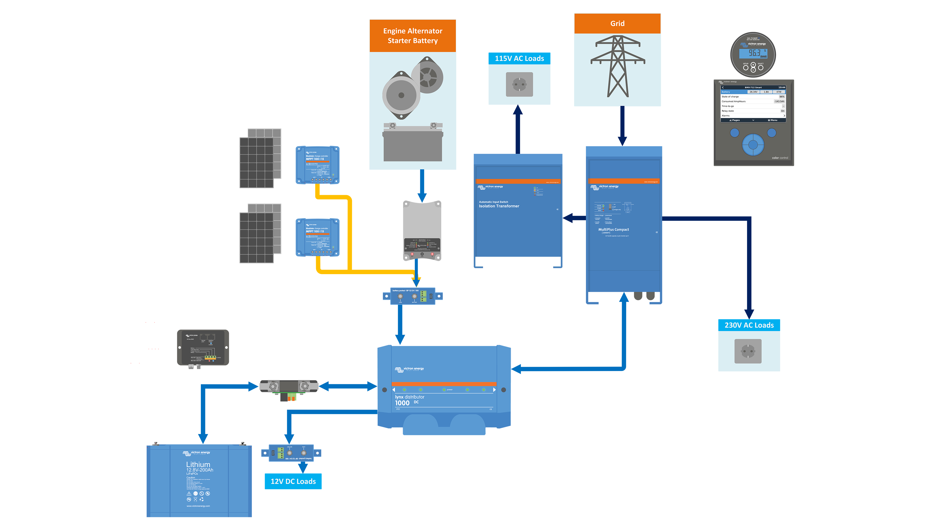
Victron VW Van Electrics Install - Schematic Drawings


You may have seen our VW Van videos on YouTube.

If you haven't here is a link to them:
Episode 1 - Solar: https://youtu.be/YW_xDerTycQ
Episode 2 - Alternator: https://youtu.be/vCOJ3nBFpIM
Episode 3 - Mains Electricity: https://youtu.be/TDSzfmHHjsA
Episode 4 - Color Control & Battery Monitor: https://youtu.be/2PyMIndbz6w


Here are the slides for the concept:

Single Line Diagram PNG images

Overall Idea

Solar Idea

Alternator Idea

Single Line Diagram PDFs

SLD - Victron Van - Automotive - Alternator.pdf

SLD - Victron Van - Automotive - Overall.pdf

SLD - Victron Van - Automotive - Solar.pdf


After lots of tweaks and changes, here are the schematic drawings for each section of the vans install:

Detailed Schematic PNG Images

Solar

Alternator

Mains Electricity

Full Schematic Wiring Diagram

Detailed Schematic PDFs

DS - Victron Van - Automotive - Alternator.pdf

DS - Victron Van - Automotive - Full.pdf

DS - Victron Van - Automotive - Multi.pdf

DS - Victron Van - Automotive - Solar.pdf


wiringwiring diagramcampervanschematics
32 comments
2 |3000

Up to 8 attachments (including images) can be used with a maximum of 190.8 MiB each and 286.6 MiB total.

JohnC avatar image JohnC ♦ commented ·

Thank you Jono. Destined to become a standard reference, so if you do make 'improvements', please let us know. Cheers.

0 Likes 0 ·
Show more comments
wkirby avatar image wkirby ♦♦ commented ·

Thank you Jono!

0 Likes 0 ·
boekel avatar image boekel ♦ commented ·

Why is there a smart battery sense? doesn't the VE.bus BMS send all values to the system?

0 Likes 0 ·
Show more comments
veganvanlife avatar image veganvanlife commented ·

Hi there, can anybody shed some light on whether the BuckBoost connects to the starter battery or the alternator? I plan to install a 50A BuckBoost in my 2015 Sprinter 313.


Kind regards, Tom

0 Likes 0 ·
Show more comments
eliott avatar image eliott commented ·

Hi!

In the video, it is said that the current limiting will be done in the CCGX. Is it a new feature of the MultiPlus II? I thought that all VE.Bus BMS systems needed the Color Control as the current setting in the CCGX is disabled.

0 Likes 0 ·
Show more comments
nebulight avatar image nebulight commented ·

This is almost EXACTLY how my van is setup minus the transformer. I assume the Battery protect is going through the BMV for relay settings for cold weather charging prevention since you can't control the buck/boost via the venus? I have a DC-DC battery charger and that's how I set mine up. I'd just like clarification as I get a lot of questions about my van setup and it would be nice to just point people to this thread.

0 Likes 0 ·
Show more comments
Tim from Eat Sleep Van avatar image Tim from Eat Sleep Van commented ·

Hi I'm confused how the Buck/Boost converter is connected to the battery. From the video and wiring diagram there is only 1 cable connecting positive output from the converter to the house battery positive. I'm definitely no expert but I thought you need a circuit for electricity to flow?! I see the alternator has both positive/negative. What am I missing?!

0 Likes 0 ·
Show more comments
Tom avatar image Tom commented ·

1) In the VW Van build video 4 it talks about connecting the ColorGX to the VW screen, but then the video does not speak of it? How do you get the color GC scream on say a VW, MB or a double din radio screen?

2) is it possible to use the Victron Buck converter in a 12-14.4 Volt alternator to charge a 24 volt battery bank?

3) the 12/2000 Multiplus has a 4 amp charger connected to the car starter battery. Can a 24/3000 Multiplus charge a car battery at 14.2 volts?

Tom


0 Likes 0 ·
Show more comments
kiko avatar image kiko commented ·

Hi Jono, thank's so much for this reference. It was extremly helpful! I just built a 24V system based on your design.

I am using Smart Battery Protects 220 and found out, that I have to use the Remote H pins to get everything to work. First I was confused by the the drawing, as on your BPs, the pins used are the ones on the "inside", also wihtout a label. On mine it's the outside ones.

Looking here https://www.victronenergy.de/upload/documents/Manual-Smart-Battery-Protect-12V-24V-65-A-100-A--220-A-EN-NL-FR-SE-DE-PT-ES-IT.pdf on Figure 5, it becomes obvious.

Can you confirm this?

Regards


0 Likes 0 ·
Show more comments
kiko avatar image kiko commented ·

I was also wondering about the settings for the BMV 712. I used the following logic:

• Battery Capacity: Total battery capacity in Ah - obvious, I used the 25°C value, 400Ah in my case
• Charged Voltage for Victron Lithium: Absorption voltage 14,2V - 0,3V = 13.9V for 12V and I guess -0,6V for a 24V system, so 28,4V - 0,6V = 27,8V
• Tail Current: 2%
• Peukert Exponent: 1.05
• Charge Efficiency Factor: 99%

I used these sources:

https://www.youtube.com/watch?v=yMJ_vzB2avE

https://amsolar.com/s/BMV-712-in-App-for-Victron-Lithium-46cy.pdf

0 Likes 0 ·
Show more comments
kiko avatar image kiko commented ·

I also wanted to mention the relais settings I used on the BMV which has a temperature sensor in my case. I set the minimum charge temperature on the MPPT to 8°C.

I have learnt, that is is not good for the MPPT to disconnect it from the batteries while charging using the BP. So I set the low temperature relais in BMV to close at 5°C and reopen at 7°C.

This way, the MPPT should have stopped charging, before the BP closes and turns off the Buck Boost.

Would you agree with this logic?

Why isn't the BMS using its charge disconnect directly in case of a low temperature event? The information and the configuration seems to be present within the batteries.

0 Likes 0 ·
Show more comments
georgejt avatar image georgejt commented ·

Hi. Is there any reason why the multi plus inverter was not also run through a battery protect? Excuse my ignorance, new to this. Thank you.

0 Likes 0 ·
Show more comments
scf avatar image scf commented ·

Thanks for posting this.

In the diagram DS-Lucians-Victron-Van-Automotive-Full.pdf, where is the connection from the starter battery negative terminal to anything except the 50A buck-boost and battery protect device? There needs to be a current path to the bus bar GND as well.

0 Likes 0 ·

Article

Contributors

Guy contributed to this article jono contributed to this article

Related Articles