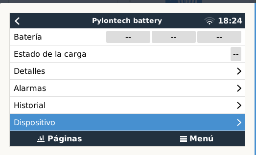
I have 2 modules of pylontech US2000C and it shows not connected, I cannot see the parameters, in the cerbo GX it is connected to the BMS-CAN with can type A cable. How can I solve see the batteries connected?

This site is now in read-only archive mode. Please move all discussion, and create a new account at the new Victron Community site.
Check the wiring. The CAN cable is labeled with "Victron CAN" and "Battery CAN". The Victron side have to be connected to the Cerbo and the battery side to the battery the connector labeled with "A/CAN".
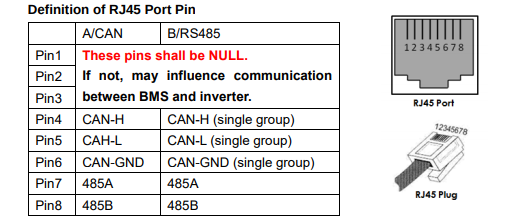
Thank you, the battery is US2000C and uses CAN A cable, I had purchased the CAN type B, since I did not expect the US2000C battery model in the purchase of equipment, if not the US2000. I wrongly modified the side CAN type A. Through the Victron document of the CAN A protocol with pylontech I saw the pins that change, pin 3, 7 and 8 change to 6, 4 and 5, you could help me tell me how is the order of colors of the cables for CAN A, and I can verify that I do it well, I do not have the cable quickly available through Victron because I am in an area very far from the city, then I would replace it when acquiring it.
The VE.CAN side:
1 white / orange
2 orange
3 white / green = GND
4 blue
5 white / blue
6 green
7 white / brown = CAN-H
8 brown = CAN-L

Side BATTERY CAN TYPE A:
1 white / orange
2 orange
3 green
4 white / brown = CAN-H
5 brown = CAN-L
6 white / green = GND
7 blue
8 white / blue
I would be very grateful to check the color order
You have used all 8 wires. According to the Pylontech manual, you should only terminate the pins that you need.
You should only use one pair for pins 4 and 5 and another colour for the GND wire on pin 6 for the battery end of the cable.
Wiring pins that are not required may affect communications:
33 People are following this question.