Hello,
I've searched and cannot find an answer to the question I have. I have 2 x 100Ah poweroad infinity LiFePO4 batteries - and after noticing that they were discharging/charging with different loads via the inbuilt BMS I contacted the vendor who put me in touch with the manufacturer. The manufacturer has suggested rather than a typical parallel wiring configuration (+ve terminals connected, -ve terminals connected, then a take off from 1 battery's +ve terminal to the load, and from the other battery, the negative feed), they've suggested that I have take offs from BOTH battery +ve and -ve terminals into the respective +ve and -ve busbars I have on my system. Whilst I'm not that familiar with it batteries I was a bit surprised at this suggestion - but I'm about to do it as currently I have this abnormal load + cell balancing going on (I'm sure its the BMS personally...)
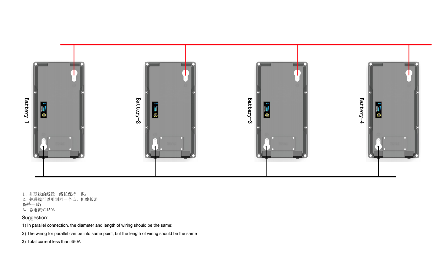
Here's the wiring diagram that they've supplied me with.

For completeness, their reply to my question was as follows:
Thank you for getting in touch
Your method or wiring is absolutely fine for a Lead acid Battery fit out, but not the ideal recommended way for lithium
This is because the current flow (red cable) goes to the battery on the left ….  And then has to decide how much current goes through the left battery and then how much goes through the right hand battery …….  There’s no guarantee that the current  will split equally
(same on the negative side)
So the cable 1 (charger) should go to the busbar – and a cable OF EQUAL LENGTH – from each battery to the busbar
Same for the negative - - cables of the same length form each battery to the busbar
Fundamentally there’s nothing really wrong in what your have done (don’t get concerned) , but getting the exact cell balancing won’t occur automatically
If you use the app you might find there are different Voltage rating on the cells ……. However the batteries will readjust in time
Its just your app will show a variation
Therefore to get over this and do it correctly, which is better longer term, if you can change to what I am suggesting would be better
Anyway, in the meantime I bought a smart shunt. With the docs saying that this should be the only thing on the negative battery pack terminal to measure the current correctly how should I wire this up?
There's two possible options that I'm thinking of:
1) BOTH -ve batteries connecting to the shunt, then the shunt to my -ve busbar if I can get the terminals on there.
2) An intermediary -ve busbar, where the two batteries connect to this new bus, along with the shunt, which then feeds my system -ve busbar?
Any help would be greatly appreciated.
Thank you.
