Hi guys.
I am about to install the 500A/50mV-Shunt to my self-made battery (LiFePo4) system and bought the correct temp sensor for the connection with Vbatt+ and Aux.
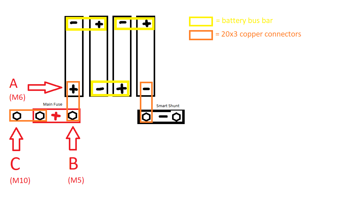
As I have connected my cells main positive to a copper strip (20x3mm) in order to be able to use bigger lugs (the battery cells only have M6), and the heavy duty lug on the temp sensor has a M10 hole, I was wondering where I should ideally connect it:

A, at the raw cells’ main positive
B, at the battery input of the main fuse, supplying it with power even when the fuse has blown.
C, at the fuse output, NOT supplying it with power, after the fuse has blown, but with a fitting M10 bolt. This is where I will connect the distribution bus bar with all my loads and chargers.
Also, I was wondering whether I could install a manual switch in the positive cable of the temp sensor, making it possible to turn off the shunt and prevent micro current in case I want to store the battery.
I have a Victron Smart Solar MPPT, BlueSmart IP65 and Orion-Tr in my setup. Am I understanding it correctly that the temperature sensor of the SmartShunt supplies all of these with the temperature reading when in the same network as the others, in order to optimize charging?
Thanks in advance for your answers!
Jacob
P.S.: Of course, I have a BMS between the battery main negative and the shunt, I just didn’t draw it in the above scribble, as the temp sensor should be connected to the positive side, as shown in the manual.
