Could someone please share how they wired an auxiliary fan with a Multiplus 12/3000? I've read a couple other posts that mention setup of the assistants, and I've set up 2 (one ON and one OFF) through the K1 relay. However, the documentation isn't very clear on what the NO/NC/COM ports are actually doing when the assistants are setup to "turn on". I understand NO = normally open, NC = normally closed, and COM is the common. I've tried wiring a couple different ways and haven't had success with the auxiliary fan turning on following the inverter fan. It is a 12v, 0.16A 120mm computer fan. I've tried wiring directly to the K1 relay port, using the NO as power supply and common as battery negative. I've also tried providing power separately via a 4-pin relay, treating the NO port like a switch+.
- Home
- Anonymous
- Sign in
- Create
- Spaces
- Grafana
- Node-Red
- Unsupported topics
- Questions & Answers
- Modifications
- Communauté francophone
- Deutschsprachiger Bereich
- Preguntas en Español
- Explore
- Topics
- Questions
- Ideas
- Articles
- Badges
question
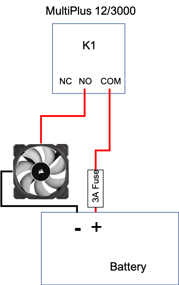
The relay acts like a switch. Connect the negative of the fan directly to the negative of the battery (or the negative post inside the MultiPlus), a wire from the positive through a fuse to COM and from NO to the positive of the fan.
Matthias, thank you for the quick reply! Just want to confirm my diagram below represents your suggested solution. It wasn't clear if you meant connect COM to BATT+ or FAN+. I think you meant BATT+ since you said it is a switch and this implies power isn't routed through the Multi. I chose a 3A fuse since the data sheet mentions the relay is rated to 4A at 12V.
Thanks again!

Just to confirm Tony's answer, "relay closed" and "relay open" are not the language in the assistant. It shows "relay ON" and "relay OFF". Does "closed" refer to "ON" and "open" refer to "OFF"? So if I wire via NO and COM, the relay ON setting will close the relay and provide power to the fan, and the relay OFF setting will open the relay and cut power. Correct? Or do I have it backwards?
Also, I'm assuming it doesn't matter whether wiring the fuse to COM or fuse to NO, with the fan positive wired to NO or COM respectively?
I've done it the way I've described on my Quattro 12/5000. Weirdly, the Quattro manual does not show the presence of the multi purpose relay in its diagrams. I find these kind of documentation gaps very frustrating.
I believe the "normally" state is the state when the relay is "off", so NO (Normally Open) is open when "off" and NC (Normally closed) is closed when "off", then switch to the opposite when "on".
The above diagram works a treat. Using mine now and being on a narrowboat, it does get very hot on board. So, now I have two external 80mm fans running on my cabinet when turned on by this relay so the cabinet keeps cooler. I may have to increase the size of these fans if they are not sufficient.
question details
49 People are following this question.
