question

jlursocal avatar image
jlursocal asked

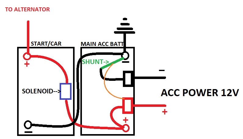
BMV Not Detecting charge from Vehicle Alternator - Genisys Dual Battery system

I have a 712 BMV. I have it working in combination with a Genisys Dual Battery system for Jeeps. It works great and detects a charge if I charge my batteries using my solar (100/20 MPPT Victron charge controller ) which is connected to the ACC Power bus bars. When I drive the car however, the BMV never changes/detects the SOC regardless of battery voltage or Output (negative)... the SOC continues to drop...

The solenoid (in the picture) joins the 2 batteries when the starter battery ( the one on the left) is over 12.8 volts.

Attached is a diagram of the device and they way I have it hooked up.

Can any one explain why it will not detect the charge from the cars alternator and/or potential fixes?

thank you in advance.bvm-genisys.jpg
BMV Battery MonitorSOC
bvm-genisys.jpg (58.0 KiB)
2 |3000

Up to 8 attachments (including images) can be used with a maximum of 190.8 MiB each and 286.6 MiB total.

2 Answers
Murray van Graan avatar image
Murray van Graan answered ·

Hi @JLURSoCal

The issue is that the current flowing from the car alternator is not flowing through the BMV shunt. You can rectify this by mounting the shunt between chassis ground and battery negative, and also taking the ACC busbar negative from the chassis. That would ensure ALL currents are flowing through the BMV shunt

5 comments
2 |3000

Up to 8 attachments (including images) can be used with a maximum of 190.8 MiB each and 286.6 MiB total.

jlursocal avatar image jlursocal commented ·

Just so I understand, I should connect the end of the shut that is currently connected to the neg terminal on the battery to chassis ground, and the other end of te shunt to the battery's negative pole. Also I would connect the Acc negative direct to ground.

correct?

0 Likes 0 ·
Murray van Graan avatar image Murray van Graan jlursocal commented ·

Correct

0 Likes 0 ·
jlursocal avatar image jlursocal Murray van Graan commented ·

thank you !

0 Likes 0 ·
jlursocal avatar image jlursocal Murray van Graan commented ·

After letting this answer soak in overnight, I have a couple questions.

If I do connect the Shunt this way, wouldnt it pick up not just those items connected to the bus bar but rather everything pulling energy from both batteries? (having a hard time wrapping my head around this)

Also would it make a difference if I connected the neg bus bar direct to the battery neg as apposed to the chassis. the chassis is directly connected to that neg battery terminal already... I dont know how this would make a difference by connecting the neg bus direct to ground...

I appreciate you help!

0 Likes 0 ·
Murray van Graan avatar image Murray van Graan jlursocal commented ·

Aahh yes you are correct. To eliminate that, the starter battery negative should also be wired directly to the chassis ground, and the ACC battery negative will be connected via the Shunt. The rest can still be wired as we discussed. So then, the starter battery current will not flow through the Shunt.

0 Likes 0 ·
wkirby avatar image
wkirby answered ·

There is no charge current from left battery to right battery going through the shunt, the negative is going directly to the right battery negative terminal. That is your problem, it is impossible to the BMV to detect this charge current if it does not pass through the shunt.

Connect negative cable from left battery to the LOAD / CHARGE terminal of the shunt, then it will work.

1 comment
2 |3000

Up to 8 attachments (including images) can be used with a maximum of 190.8 MiB each and 286.6 MiB total.

jlursocal avatar image jlursocal commented ·

I thought of that as well, as putting the shun in-line between the 2 neg battery terminals.

If I did it your way, what AWG wire you think i should use?

thanks for your input!

0 Likes 0 ·

Related Resources

Additional resources still need to be added for this topic