question

technomadia avatar image
technomadia asked

Feature Request: Use AC2 Output As a Diversion Load

I am assuming it is not possible with current hardware - but while brainstorming with several other Victron users we were wishing that the AC2 output of a Multi or Quattro could be used for diversion loads to put excess solar power to use automatically.

I know you can accomplish this already with the relay output on the BMV and an external relay - but it would be really convenient in many installations if the internal AC2 relay could handle the job.

Might this ever be possible? Is it perhaps possible on current hardware with a firmware update?

MultiPlus Quattro Inverter Charger
2 |3000

Up to 8 attachments (including images) can be used with a maximum of 190.8 MiB each and 286.6 MiB total.

8 Answers
boekel avatar image
boekel answered ·

It is already possible, you can switch on AC2 based on a lot of conditions, when using Lithium batteries it's really easy: just use battery voltage as a trigger. (or SOC if you prefer)

2 |3000

Up to 8 attachments (including images) can be used with a maximum of 190.8 MiB each and 286.6 MiB total.

Guy Stewart (Victron Community Manager) avatar image
Guy Stewart (Victron Community Manager) answered ·

To expand on Boekels answer; This is possible and done through the Programmable Relay (Use ACOut2 relay) assistants functionality in VEconfigure.

You can test the functionality in VEconfigure by loading up the Fake Target dummy with full options before actually programming your Multi.

It would be great if you/someone could write up a more extensive description, step by step of what you do, and screenshots to help others in the future.

This documentation could definitely use some expansion and improvement:

https://www.victronenergy.com/live/assistants:start

1 comment
2 |3000

Up to 8 attachments (including images) can be used with a maximum of 190.8 MiB each and 286.6 MiB total.

Rob Duthie avatar image Rob Duthie commented ·

Hi Guy

I have done Hot water diversion test using the gen start and using the programmable relays with SOC charge high and low % values so as not to over load the inverter when other loads might come on which are more critcal.

Update and tested on the 30/03/2021 on the Hotwater diversion control assistant setup below is the only one that works well with the gen start using the programmable relay. with no AC input otherwise its keeps the relay on all the time, I think Victron should add another assistant called Diversion control so not to confuse it with the gen start assistant, just a thought?


*) Use primary programmable relay to start generator.

*) Open relay to start generator.

*) Start generator when load higher than 2500 Watt for 5 seconds

and stop generator when load lower than 2000 Watt for 5 seconds.

*) The generator is not stopped by AC input.


programmable relay (size:30)

*) Use primary programmable relay.

*) Set relay on

*) when SOChigher than 99%.


programmable relay (1) (size:30)

*) Use primary programmable relay.

*) Set relay off

*) when SOClower than 98%

Regards

RobD
NZ

0 Likes 0 ·
boekel avatar image
boekel answered ·

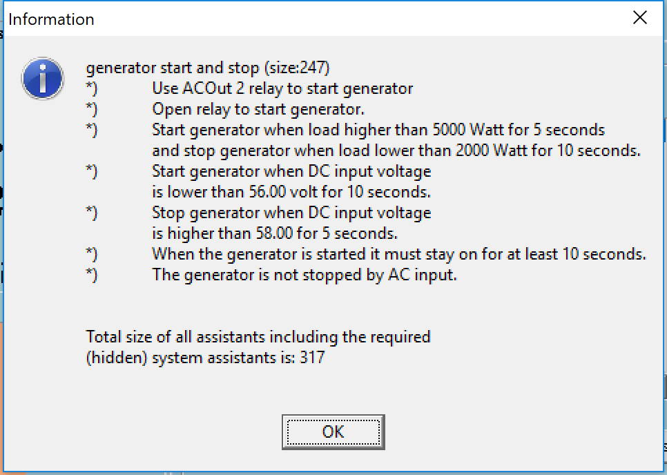
Here's an example of using the generator start/stop assistant, dump load connected to AC-out 2:

'open relay to start generator' - this inverses the logic

'start generator on load': this is actually stopping the dump load (remember we inversed the logic), even when battery voltage is higher than the set 'dump' voltage:

'start generator when load higer than 5000 W' - let's say the dump load is 2000 W, if a lot of other loads are on, you might want to turn of the dump load to prevent overloading the inverter.

'stop generator when load is lower than 2000 W' - when other loads are lower, start the dump load

'Start generator when DC input voltage is lower than 56 volt' - this stops de dump load when battery voltage sags under 56 volts

'stop generator when DC input voltage is higher than 58 volt' - this starts the dump load when battery gets above 58 volt.


On systems with Li-ion batteries, I'd use switching based on voltage, although if you have a reliable SOC from a BMS this should also work.

On systems with Lead-Acid batteries, I'd use SOC as a trigger, but you can ad a secondary trigger on voltage also to prevent errors. (I don't work much with Lead Acid batteries anymore)


1 comment
2 |3000

Up to 8 attachments (including images) can be used with a maximum of 190.8 MiB each and 286.6 MiB total.

Hi Boekel,

Would you be happy for me to use some of your work here to improve the documentation?

0 Likes 0 ·
Mark avatar image
Mark answered ·

I have also been thinking about this (to run a water heater)...

Like most, my aim of the logic would be to only run the load when batteries are full & when there is enough PV power to support the load without draining the batteries.

If possible I would even like to avoid small 100% to 95% SOC cycles...

My thinking is that a reasonable way achieve this fairly easily would be with the following conditions (mainly with reference to BMV data);

TURN ON conditions;

If SOC is >98% AND if MPPT 'awake' (panels irradiated) AND both conditions maintained for >15 min then turn ON

TURN OFF conditions (that also kind of act as a basic PV available power check);

If there is a Battery Current DRAIN >1 Amp & maintained for >30 sec then turn OFF

OR if SOC is <95% OR if Voltage is <x V (just as a safety measure)

Using a large time condition (ie 15 or 30min) for the turn ON condition will avoid the load switching on & off consistently/frequently if the battery is full but there is not enough PV to support the load (without draining the battery).

As a result it should only be possible for the load to turn ON once 15 or 30 minutes and then 'check' if there is enough PV / charge current available to cover the load. Even in worst case PV conditions, such a short check (only as long as the turn OFF condition) will have a minimal effect on the battery SOC.

I believe that the BMV SOC is already available to use in the Multi (to use as a trigger/selection), but don't believe that BMV instant charge/discharge current is (yet) - this would probably be the main missing link...?

The small downside to this logic is that during the later stages of Absorption period the charge current would drop off (meaning significant unused PV power during this period of time), but the SOC condition will not yet be met until the battery is fully charged (basically after going into float).

To rectify this the SOC % used to turn ON could be lowered but then you could risk not fully charging the batteries in the same day... (if there is not enough power for the load & for charging simultaneously) Potentially the logic could be 'complicated' even further by adding a different/additional OFF condition that is only active for times when SOC is <95% (to ensure sufficient charge current is still flowing to the battery).

Any thoughts from anyone more deeply involved?

Does the 'basic' version seem reasonable to implement with only a few additional parameters provided to the Multi?

Regards, Mark.

11 comments
2 |3000

Up to 8 attachments (including images) can be used with a maximum of 190.8 MiB each and 286.6 MiB total.

boekel avatar image boekel ♦ commented ·

First: what kind of batteries are you talking about?
Second: a current drain of 1A will happen all the time, except if all loads are constant.
third: why are you concerned about batteries cycling 95-100%?

0 Likes 0 ·
Mark avatar image Mark ♦♦ boekel ♦ commented ·

Hi Boekel,

My battery bank is VRLA AGM. Please don't pay too much attention to the exact numbers that I have 'plucked out' - they were just an initial guess to convey my thinking and would need to be tuned in conjuction with the associated time condition to best achieve the desired result.

My expectation is that the load will cause a voltage drop and then the MPPT will quickly respond by altering its output to maintain the voltage setpoint while also powering the load.

If it can acheive this well enough there should be no notable drain from the battery and definitely nothing sustained for an extended period.

I would 'prefer' to not have multiple small battery cycles each day due to the effect (however small or large) on battery life.

So the aim with my logic is to only run the load when batteries are full & the PV CAN keep up.

The batteries would only have to cover during times of fluctuation. The OFF current & timer can be relaxed to prevent false OFF triggers.

0 Likes 0 ·
boekel avatar image boekel ♦ Mark ♦♦ commented ·

I think with lead-acid it can only work if you size your dump load to a lower power than the PV minus 'normal loads' , this way the MPPT's can continue to provide float voltage.

It will always be difficult with lead-acids, as during the absorbtion stage the current absorbed by the battery reduces, so you always wast energy until the battery is finally charged...and when it's finally charged the sun might already be on it's way down.

0 Likes 0 ·
Mark avatar image Mark ♦♦ boekel ♦ commented ·

Yes I agree with both your points & was already thinking along the same lines.

Since you seem to be the 'assistant king' :-), what's your thoughts about programing in the assistant logic?

What conditions are currently missing in the Multi?

I think that only BMV instant charge/discharge current is missing... BMV SOC is already there, correct?

To link the MPPT into the conditions I could set 'panels irradiated' as the MPPT relay output & wire it into a Multi Aux input.

Let me know what you think...

0 Likes 0 ·
boekel avatar image boekel ♦ Mark ♦♦ commented ·

I don't know if the BMV current is somehow sent to the Multi.

I think you better look into the Venus devices to incorporate the functions you want to have, as you already know it is not possible to know how much PV capacity is unused without an external irradiation sensor.
And you'll need a load that has a variable power also.

I'd just use Lithium batteries and a fixed load, this makes life a lot easier ;)

0 Likes 0 ·
Pat Davitt avatar image Pat Davitt boekel ♦ commented ·

I have an Irradiance sensor from IMT Solar in my system. That's why I asked the question I did below.

Pat

0 Likes 0 ·
Mark avatar image Mark ♦♦ Pat Davitt commented ·

Hi Pat, I agree that an irradiance sensor & related calculations (specific to the PV used) is a very good way to see whats going on & I really like your neat work in your related post.

I'm trying to achieve this on the cheap & fairly simply - by basically turning on the load for a short period of time & 'testing' to see if the PV can actually support it without draining the batteries at all (with a 'test' only occurring every 15 min or so once the basic conditions are met).

I don't know how well it will work, but that's my thinking at least....

Even though this is far from fancy or optimal, it does have the advantage of being a true test of the PV, without any theoretical background calculations that might not match reality 100%.

0 Likes 0 ·
Show more comments
Mark avatar image Mark ♦♦ boekel ♦ commented ·

The setup is at a farm & we generally only go up on weekends, so it is a little more difficult to play with / test ideas. The advantage about this is that during the week there is plenty of 'unused' PV power available.

Regarding BMV SOC being already sent to the Multi, sorry it seems that I must have thought that after briefly seeing this page; https://www.victronenergy.com/live/dc_coupling:using_bmv_soc_in_a_vebus_assistant_setup

Despite BMV SOC not being sent directly to the Multi, the BMV relay could be configured for this & wired to a Multi AUX input - probably in best series with the MPPT relay output (to know when panels are irradiated).

The missing piece would still be an instant BMV current to 'test' for sufficient PV to cover the load...

How sensitive is the Multi Aux input voltage reading? Do you think its possible to run a 2nd set of wires from the current shunt to the Multi & set a voltage trigger equivalent to the desired current?

0 Likes 0 ·
boekel avatar image boekel ♦ Mark ♦♦ commented ·

In a system with a Venus device and a BMS or Battery monitor, the Venus sends the SOC from the chosen battery monitor to the VE.bus devices, so this value can indeed be used by the assistants.

Are you talking about an AC-coupled system here? I've read about devices that can be used to keep AC output at zero by varying the load (water heater). If you'd use such a device you could activate this when SOC hits a target, thing is..you'd have to do it before the Multi begins the frequency shift...
No 'easy way' yet...

0 Likes 0 ·
Show more comments
Pat Davitt avatar image
Pat Davitt answered ·

Can the ACOut2 relay be driven high (and then low) with a Modbus TCP input to a CCGX from an external Modbus TCP Client? Would save me buying a relay for a system I'm working on.

Thanks,

Pat

2 |3000

Up to 8 attachments (including images) can be used with a maximum of 190.8 MiB each and 286.6 MiB total.

technomadia avatar image
technomadia answered ·

It is great to hear that the relay hardware is already capable of this - and I will start to play around with assistants.

Here is the logic I would like for the AC2 relay:

+ If on shore power, open the relay and pass through the power.

+ If on generator power, once the battery has reached 90% charged open the relay and pass through the power.

+ If on inverter and charging via DC solar, engage the relay when the battery reaches 90% and disengage when it hits 80%.


And of course - there should be a way to manually override this automatic logic.


This would let all excess power very nicely flow into the hot water heater hooked up to AC2.


Any thoughts on how to implement this are appreciated.

2 |3000

Up to 8 attachments (including images) can be used with a maximum of 190.8 MiB each and 286.6 MiB total.

Francis Hemeter avatar image
Francis Hemeter answered ·

My understanding from he above I could use the following to switch hot water system on and off

*)Use ACOut2 relay to start generator


*)’open relay to start generator' - this inverts the logic

(start generator = open relay to turn off ACOut2)


*)’start generator when load higher than 5000 W for 5 seconds’ -and

Open ACOut2 when load higher than 2400W for 10 seconds

Turn off hot water when load higher than 2400W for 10 seconds

'stop generator when load is lower than 1800 W' -

Close ACOut2 when load is lower than 1800W

Turn on the hot water when load is lower than 1800W for 10 seconds


*)’Start generator when DC input voltage is lower than 26.5 volt' -

Open ACOut2 when DC input voltage is lower 26.4

Turn off hot water when voltage is lower than 26.4 will have to experiment with this to get about the SOC I want especially with voltage sag.


*)stop generator when DC input voltage is higher than 26.61 volt' -

Close ACOut2 when the DC voltage is above 26.61

Heat hot water when the voltage is above 26.61


*)When the generator is started must stay on for a least 10 seconds

When ACOut2 is Open and the hot water system is off must stay off for 5 minutes longer.


*)The generator is not stopped by AC input

I am not sure about this command, I assume it applies to the assistant as a whole, that is not effected by inverted logic with the start/stop, but will allow the assistant to run or remain in its current state even if AC input is active. That is I have shore power.


2 |3000

Up to 8 attachments (including images) can be used with a maximum of 190.8 MiB each and 286.6 MiB total.

Rob Duthie avatar image
Rob Duthie answered ·

Would this logic work as water heater control with load diversion and with inverter overload protection?

TAB: Assistant Configuration

programmable relay (2) (size:186)

*) Use primary programmable relay.

*) Set relay off

*) when load higher than 2500 Watt for 10 seconds.


programmable relay (3) (size:47)

*) Use primary programmable relay.

*) Set relay on

*) when load lower than 2000 Watt for 10 seconds.


programmable relay (size:30)

*) Use primary programmable relay.

*) Set relay on

*) when SOChigher than 99%.


programmable relay (1) (size:33)

*) Use primary programmable relay.

*) Set relay off

*) when SOClower than 98%.


Total size of all assistants including the required

(hidden) system assistants is: 368

2 |3000

Up to 8 attachments (including images) can be used with a maximum of 190.8 MiB each and 286.6 MiB total.