question

Brandon avatar image
Brandon asked

Parallel solar array wiring configuration

I am trying to figure out the best way to wire my solar array. I will be running:

6 x 370W Trina solar panels with my Smart Solar MPPT 150/100 TR (Batteries are 24v). Photo attached of PV panel specs

Each panel has a max short circuit current rating of 11.37A. So I was thinking of running a 15A MC4 fuse for each panel. But the part I'm not sure about it how many cables I should run.

For example, Should I run smaller cables from each individual panel down to my electrical box, so I would have 12 cables (6 pos and 6 neg) running down to my electrical cabinet. (This seems like alot of cables...)

or

Should I join the panels into 3 pairs of 2 with MC4 splitters, so I would have 6 larger cables (3 pos and 3 neg) running down to my electrical cabinet

or

Another configuration?


The cable run from the furthest panel from the electrical cabinet is just under 10m. So obviously whichever way I go I need the cable to be large enough to carry the current (in this case at least 15A for one panel, due to fuse size) over that distance for however many panels are feeding it but also small enough to be soldered into an MC4 connector.

I know that in some cases people use like a junction box to join the panels, but I really don't like the idea of a box being on the roof in the weather to get moisture etc inside of it. I'd prefer them to all join in the electrical box which I am planning on doing.

Sorry for the long question. Just trying to find out the proper way to do things. If that's completely different from what I'm imagining, I'm willing to embrace it.

MPPT SmartSolarSolar Panelsolar sizing
jjj.jpg (332.8 KiB)
2 |3000

Up to 8 attachments (including images) can be used with a maximum of 190.8 MiB each and 286.6 MiB total.

1 Answer
wkirby avatar image
wkirby answered ·

The ultimate way is to run a pair from each panel down to the fuse box with a fuse for each panel. This is also the rule in some jurisdictions.

It is possible to wire two panels in series and then you only need to run three pairs of cables down to the fuse box into three fuses. No junction boxes on the roof, just snap the two MC4 connectors together on the roof.
PV production will start slightly earlier in the day because of the higher PV Voltage.
This configuration is not good if you have shading issues. One shaded panel of the two will reduce the output of both.

With the 150/100 charge controller, you could even three of those panels in series for two pairs of cables down to the fuse box and two fuses. Voc would be 123.9V@25°C and Vmp would be around 102V. Ever earlier startup time, but even worse for shading issues - if you have shading issues. You'd only have to worry about getting close to the 150V maximum at around -50°C!!


11 comments
2 |3000

Up to 8 attachments (including images) can be used with a maximum of 190.8 MiB each and 286.6 MiB total.

klim8skeptic avatar image klim8skeptic ♦ commented ·

2 series, x 3 parallel's on a single pair cable to the mppt will go over the rating for of 30a per MC4 connector pair.

Best to run 3 dc pairs from each (2 series) array string to mppt.

Fusing for each string would be 1.2 - 1.5 string Isc.

0 Likes 0 ·
Brandon avatar image Brandon commented ·

@WKirby @klim8skeptic wouldn't wiring my panels in series bring down my total current output from the whole array in comparrison to them all being wired into parallel?

0 Likes 0 ·
seb71 avatar image seb71 Brandon commented ·

Wiring some panels in series will bring down the PV array current. And that is a good thing.

What you miss is that you will have higher PV array voltage.

So your total PV array power will remain the same (assuming you do not have shading issues).


The higher PV array voltage also gives your MPPT more room to track the maximum power point.

0 Likes 0 ·
Brandon avatar image Brandon seb71 commented ·

I'm well aware that wiring the panels in series raises the voltage and the wattage/current output stay the same. But I don't want that, it doesn't help me.

I want all of the panels to be in parallel so I have maximum current output to maximize battery charging capacity.

So no, I didn't "miss" the fact that panels in series raise the PV voltage, I just don't see how wiring them that way is more beneficial other than the minor gains from absorbing the sunlight a little earlier in the day.

0 Likes 0 ·
markus avatar image markus ♦♦ Brandon commented ·

Think about this: 10A x 20V = 200W and 5A x 40V = 200W

BR

0 Likes 0 ·
Brandon avatar image Brandon markus ♦♦ commented ·

Exactly...

The 20V scenario pumps 10A into the charge controller.

The 40V scenario pumps 5A into the charge controller.

So why on earth would I go and raise the voltage? I know which of the 2 options is going to charge the battery quicker...The one that puts out 10A!

0 Likes 0 ·
markus avatar image markus ♦♦ Brandon commented ·

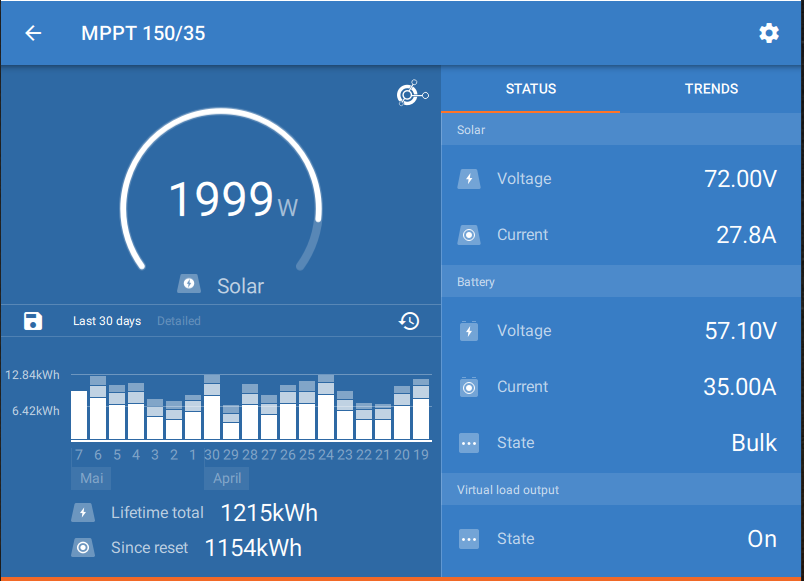
And if you look on that screenshot, you will find out that PV Voltage and Battery Voltage are not the same on a MPPT charge controller:

1620389142428.png

0 Likes 0 ·
1620389142428.png (83.7 KiB)
Show more comments
seb71 avatar image seb71 Brandon commented ·

You do miss what higher voltage means.


You are "pumping" Watts (power) into the MPPT charger.

Or, if you insist into thinking in Amps, you MUST consider Volts, too.


At the output of the MPPT charger the voltage is lower than at the input, so as a result the output current is higher than the input current.

Because Power In = Power Out (this is simplified; in the real world there are some power loses into the charger).

0 Likes 0 ·
Show more comments

Related Resources

MPPT product page

VictronConnect manual

PWM or MPPT

MPPT calculator

MPPT codes

Additional resources still need to be added for this topic