question

oemmes avatar image
oemmes asked

Strange Voltage Values and Cut Off ESS System (Multiplus, Pylontech, Smart Solar)

Strange Voltage Values and Cut Off ESS System (Multiplus, Pylontech, Smart Solar)


Hello Community,


Setup:

Victron Multi Plus 48/3000

Color Control

2 x Pylontech 2000 Batteries

Smart Solar 150/35


Im using 35mm^2 Cables with a length of 1m. The temperature is 15°C.


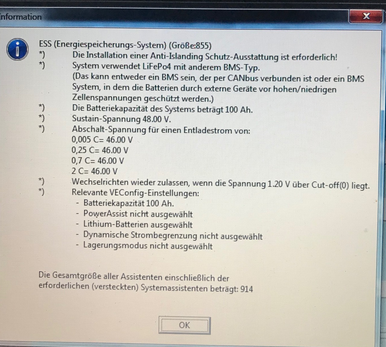
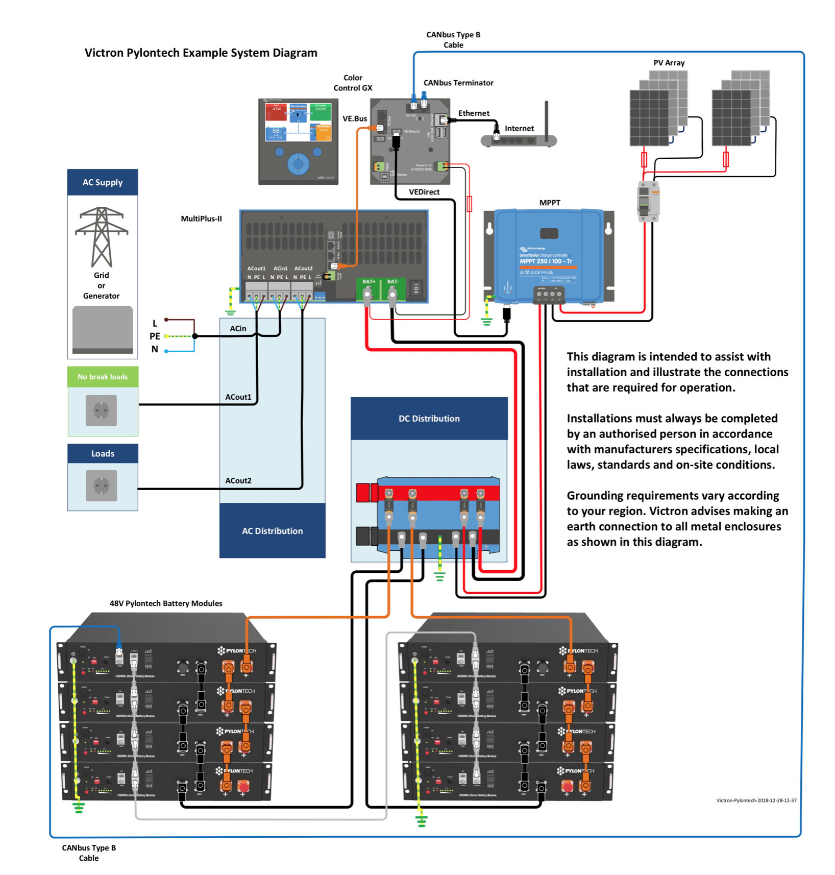
I configured my Setup with the help of this victron offical tutorial https://www.victronenergy.com/live/battery_compatibility:pylontech_phantom


Problem:

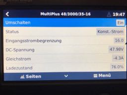
Multi Plus shows often the "Battery low voltage" warning. Especially when I have higher loads the Battery Voltage drops and the Multi Plus cuts off the batteries.

Also very strange --> Smart Solar and Pylontech BMS show both the same voltage, but Multiplus shows a different voltage value.


This setup worked for over month pretty well, but since 5 days there are these mentioned problems and the battery voltages "fluctuates".


I tried so far to reset the batteries and to program the MultiPlus / ESS again. I thought maybe its better to set the dynamic cut off values in an other way than from Victron suggested, but I don't think this would help, because sometimes the battery voltage drops to 42,7V.


Question:

What could i have done wrong ?


Thanks for the support
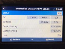
PylontechvoltageAssistants
img-0418.jpg (12.5 KiB)
img-0420.jpg (12.8 KiB)
img-0419.jpg (13.2 KiB)
img-0421.jpg (14.1 KiB)
img-0423-1.jpg (429.4 KiB)
2 |3000

Up to 8 attachments (including images) can be used with a maximum of 190.8 MiB each and 286.6 MiB total.

9 Answers
mvader (Victron Energy) avatar image
mvader (Victron Energy) answered ·

Hi. @Oemmes and rest,

To summarize all the discussions:

The issue you had was that a Battery Protect was installed in between the battery and the inverter/charger; while not suitable nor needed there. The Battery Protect broke.Taking it out fixed the issue.

To control the MultiPlus for batteries supported by us, such as the Pylontechs: no control wiring or disconnect switching is necessary at all; its taken care of by the canbus wiring and DVCC. See our battery compatibility list for which batteries we support like that; as well as the wiring diagram on the Pylontech page.

In case you have another lithium battery; not supported with DVCC; see our ‘3rd party lithium’ whitepaper on the website. But frankly to whom ever is considering such thing: why not use a lithium type we do support? There are many we do support; and using an unsupported one just means putting yourselves and your customer at risk.

Someone also mentioned that an Inverter could be switched by the BatteryProtect. Yes; in theory it can. But why do it? The better way is to switch the Inverter off by wiring its Remote on/off contact to the BMS Allow-to-discharge contact.


To summarize the three use cases of the Battery Protect:

1. As a disconnect switch for DC loads; in a system with a lead battery. Operates autonomously by measuring the battery voltage. Commonly used for this in Boats, Vehicles, and Small DC land based systems.

2. As a disconnect switch for DC loads in a Lithium system. Operated by the BMS rather than autonomously.

3. As a disconnect switch for Chargers, in a lithium system. Also operated by the BMS: the BMS asserts the control wire on a cell-over voltage.

2 |3000

Up to 8 attachments (including images) can be used with a maximum of 190.8 MiB each and 286.6 MiB total.

boekel avatar image
boekel answered ·

Did you try to measure the battery voltage at the Inverter DC terminals?
This sounds like a bad connection somewhere, quite dangerous. (when BMS and Inverter report such different values)

Also, what is the SOC when this happens? (to make sure the batteries aren't just empty)

Do you have pictures of the installation / cabling?


2 |3000

Up to 8 attachments (including images) can be used with a maximum of 190.8 MiB each and 286.6 MiB total.

oemmes avatar image
oemmes answered ·

First of all thank you for the support.


Here is the installation.

I forgot to mention that there is also a battery protect installed. Is this necessary (according to the new wiring diagram not) ?

The whole setup is build into an RV. The temperature- and voltage sensors aren't connected to the Multiplus. I think the BMS provides these information. According to the wiring diagram provided by Victron its not necessary.


I found out that the cut off doesn't depend on the SOC. It happens (f.e. at 80% SOC) when I got a greater load. A heater (1200W) is connected and when the heater turns on --> voltage drops --> Multiplus cuts-off battery.


I will measure the voltages at the Multiplus terminals this evening (when im back at my RV).


But the whole setup worked für over one month without problems.


1 comment
2 |3000

Up to 8 attachments (including images) can be used with a maximum of 190.8 MiB each and 286.6 MiB total.

Nice looking setup. Sorry to hear you are having problems.

Is the battery protect just for the multi? or other DC loads?

The battery protect can have a place in an installation like this, but it is not required. Even when switched off the multiplus has a load, and if the installation goes a long time without a charge, then the battery protect can give you an additional layer of protection from overdischarge/low voltage conditions.


That is not what you are seeing here though. And if you are having trouble isolating the source of the fault, I would probably suggest removing it for now, and see if that stops the issue.


0 Likes 0 ·
oemmes avatar image
oemmes answered ·

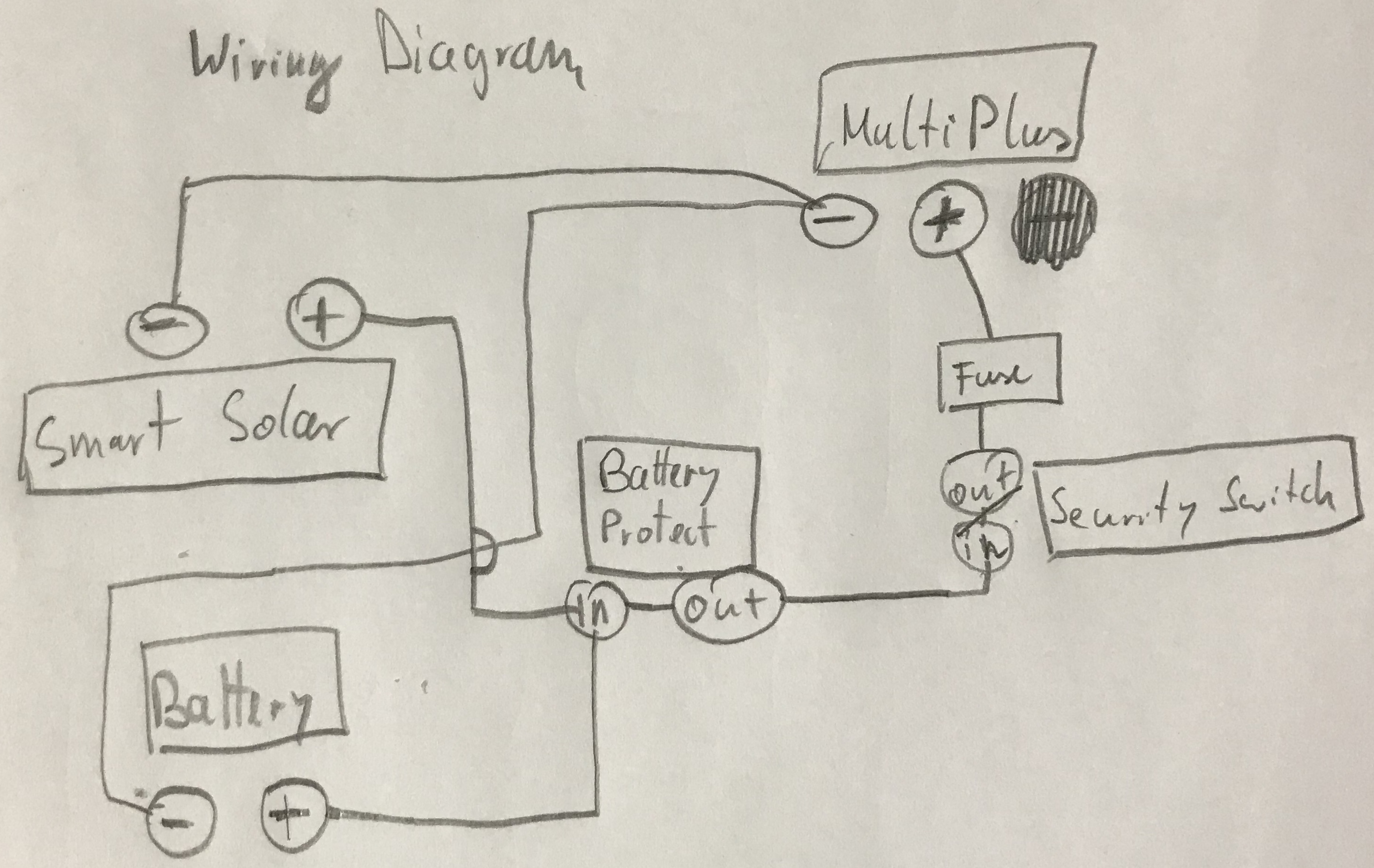
The battery protect is just for the multi. No other loads are connected to it. I guess the smart solar isn’t considered as a load. Here’s the wiring diagram with the battery protect.

I bought the setup in Nettetal/Germany at the retailer „Bosswerk“ and the technician said that a battery protect is necessary.
Nevertheless should I try to try the setup without the battery protect?

Am I Right that voltage sense and temperature sense aren’t necessary (because of the Pylontech BMS)?


12 comments
2 |3000

Up to 8 attachments (including images) can be used with a maximum of 190.8 MiB each and 286.6 MiB total.

boekel avatar image boekel ♦ commented ·

First thing you should do is measure!! have your multimeter at the battery terminals and let someone switch on a load, see what happens, than check at other points.
This way you can identify where the problem is.

Measure first...then change things. if you start by changing things you might not find the real source of the problem.

Also easy to do: load the system, than measure the voltage drop on every stretch of wiring, on the battery protect, on your isolation switch, fuse, etc. (preferably with a constant load like an electric heater)

0 Likes 0 ·
oemmes avatar image oemmes boekel ♦ commented ·

Correct. Before bypassing or changing something --> First I should measure the voltage drops in the System.

I will do this with a friend on Saturday and answer with my results.

0 Likes 0 ·

If you still have service, and you can reproduce the issue, then you should return to Bosswerk and ask for them to fix it.

If not, I would begin my troubleshooting by shutting down the system, and working through thoroughly inspecting each and every connection.

If all connections are tested and appear robust, I would move on to the battery protect. Leaving all other connections in place, I'd bypass it temporarily with a battery lead while I undertake the same testing that causes the fault to appear.

Take care not to exceed your own technical ability and confidence. This is a procedure that should be done by a technician with the proper equipment and safety precautions.

0 Likes 0 ·
oemmes avatar image oemmes Guy Stewart (Victron Community Manager) ♦♦ commented ·

I bought the parts at Bosswerk but I installed it by myself.

We all here suppose that the voltage drop issue is because of an error in a connection. Curious that it appeared suddenly, but it is as it is.

So i will measure the voltage every connection.

I will do this with a friend on Saturday and post with my results here.


Thank you for your help

0 Likes 0 ·
boekel avatar image boekel ♦ oemmes commented ·

it is not said that the voltage drop (if there is a voltage drop) is from a loose connection, but it's the first thing and easiest thing to check.

if it's not a voltage drop, than the problem can be deeper in the system.

On a relatively new system, especially one that is not stationary, a loose connection is a real possibility (it shouldn't occur when using correct components, torque and cable guiding, bus still)

On another note: on your photo it looks like there is water on the ceiling?

0 Likes 0 ·
oemmes avatar image oemmes boekel ♦ commented ·

Its not water on the ceiling. It’s old glue because the system is installed in the generator compartment. Noise cancelling mats were glued in and i removed them.


I found time and could check it today.


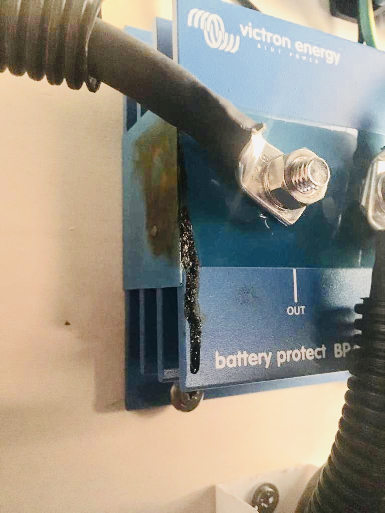
Its the battery protect. Its defective. The voltage before the battery protect are stable and realistic (50,2v).

The voltage after the battery protect is spinning. Means that it goes up to 52v and drops to 42v and so on.


It looks like the battery protect died.


It is rated for 48v and up to 100A

The maximum load of my system is limited to 50A (2x25A Pylontech).


What do you think? What could went wrong.


0 Likes 0 ·
ben avatar image ben ♦ oemmes commented ·

I can’t tell from your diagrams. Do you have a fuse or other overcurrent protection in between the battery and the BP? It doesn’t look like it. How do the Pylontech batteries limit you to 50A... or is that just the specification, and your circuit has to enforce that limit?

Your “load” (the inverter) can easily draw more than 100A. It can draw way more than that when you first connect it, if it sees the battery first, because there are buffer capacitors that are charged. You can easily ruin a BP with that, and so you either need a pre-charge circuit or you need to guarantee that you always power your inverter up first from a mains supply and then bring the battery in circuit.

Or, if that didn’t do it, your inverter is quite capable of drawing more than 100A for a short while (at peak loads).

1 Like 1 ·
ben avatar image ben ♦ oemmes commented ·

I don’t like the BPs for power systems where it counts. They fail strangely (witness your wobbling DC voltages), they tend to fail closed when they do die, and they’re asymmetric and so only provide protection in one direction.

Use real fuses for overcurrent, and use a real contactor for battery disconnect, if appropriate/desired. (And, yes, if your Pylontech batteries don’t have the ability to isolate themselves, you do need a contactor and a monitoring system.)

0 Likes 0 ·
oemmes avatar image oemmes ben ♦ commented ·

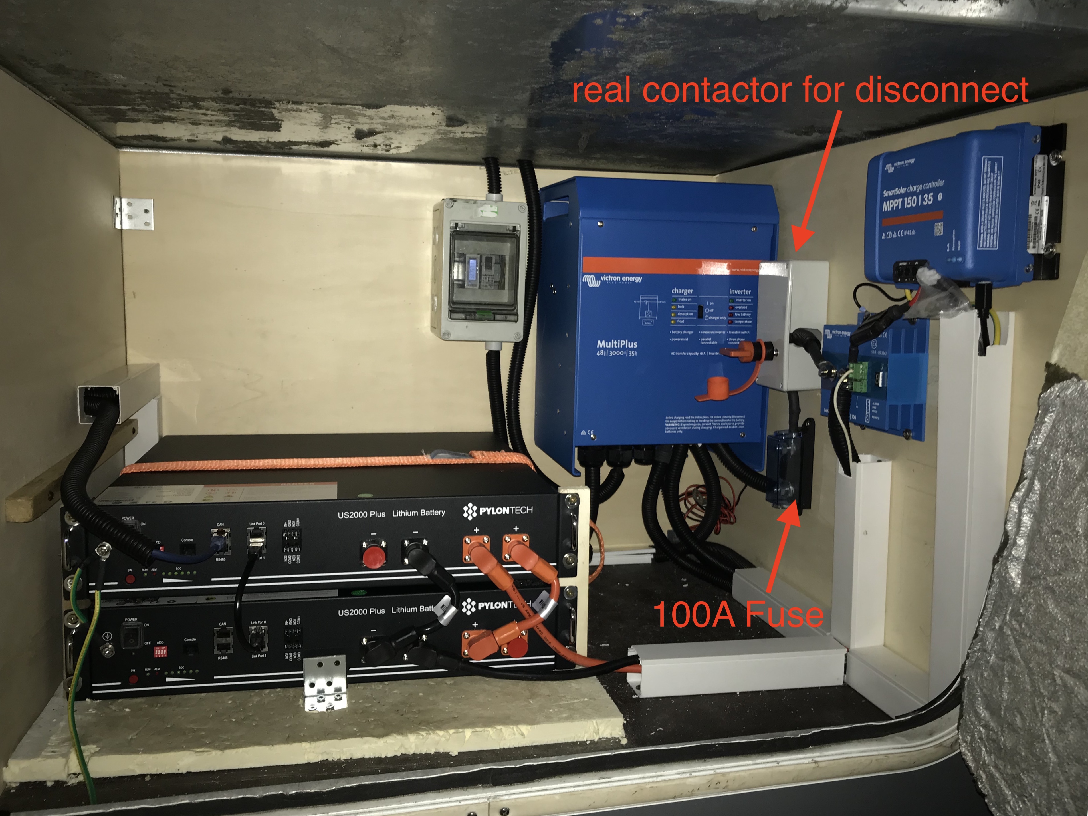
i have a overcurrent protection in between the Multi Plus and the battery protect. The fuse is also from Victron and rated with 100A so I don't think that more than 100A could be taken from the battery protect.

i marked the fuse in the wiring diagram.

0 Likes 0 ·
victron-wiring.jpg (986.1 KiB)
oemmes avatar image oemmes oemmes commented ·

fuse and real contactror are installed.

The Pylontech have also an under/overvoltage protection installed. I asked the retailer for what do I need this additional battery protect and he told me that I need it to prevent the battery from discharging critically. It seemed not logical to have to protections but when you buy a setup for 7000€ you also buy a battery protect for 140€ :)

0 Likes 0 ·
1175-img-8326.jpg (2.1 MiB)
Show more comments
boekel avatar image boekel ♦ commented ·

and yes, voltage is being sent by the BMS, if you have set everything correctly in the Venus (battery monitor --> bms and DVCC enabled).
The Multi should give an error if voltage drop is to big, but I don't know when it actually does this (it might do it now with the low voltage error).


0 Likes 0 ·
oemmes avatar image
oemmes answered ·

Here a picture


2 |3000

Up to 8 attachments (including images) can be used with a maximum of 190.8 MiB each and 286.6 MiB total.

oemmes avatar image
oemmes answered ·

Here the picture

2 |3000

Up to 8 attachments (including images) can be used with a maximum of 190.8 MiB each and 286.6 MiB total.

oemmes avatar image
oemmes answered ·

Could check it.


Its the battery protect. Its defective. The voltage before the battery protect are stable and realistic (50,2v).

The voltage after the battery protect is spinning. Means that it goes up to 52v and drops to 42v and so on.


It looks like the battery protect died.


It is rated for 48v and up to 100A

The maximum load of my system is limited to 50A (2x25A Pylontech).


What do you think? What could went wrong.


3 comments
2 |3000

Up to 8 attachments (including images) can be used with a maximum of 190.8 MiB each and 286.6 MiB total.

oemmes avatar image oemmes commented ·

Yes its the 48V 100A Version of the battery protect.

"BatteryProtect BP 48-100"


I don't know why it broke or what is wrong. I hope/guess that the reason was the battery protect itself and not the wiring or an incompatibility with the whole system.

0 Likes 0 ·

You can safely remove it from this system in any event. It is not necessary.

0 Likes 0 ·
oemmes avatar image oemmes Guy Stewart (Victron Community Manager) ♦♦ commented ·

ok thanks. I removed it and everything is working fine again :)

0 Likes 0 ·
boekel avatar image
boekel answered ·

Ahh that looks quite defective indeed..

100A is a bit on the small side I'd say, but according to the datasheet it should handle 100A continiously (250A peak)

is it a 48v battery protect?

what could be hard on the battery protect is if it is used to connect the inverter, charging the capacitors gives a big surge, but I don't know if that would be a problem.

2 |3000

Up to 8 attachments (including images) can be used with a maximum of 190.8 MiB each and 286.6 MiB total.

Paul B avatar image
Paul B answered ·

I have seen this issue and This is the cause

The BATTERY PROTECT SHOULD ONLY BE USED ON A INVERTER ONLY or a LOAD ONLY SITUATION.


The battery protect should NOT BE INSTALLED LIKE THIS IT WILL FAIL in this sort of instalation


Why

In this stiuation if the inverter/charger is charging and the Battery protect is switched off pin 1 and 2 are opened (for some reason)

when power/AMPS (IE charging the battery) is flowing to the OUT to the IN of the battery protect then it will fail in time,

The BP does not turn off when current flows OUT to IN and a resistance then occurs when current is flowing on the BP in that direction and then it overheats and fails.

THE BP MUST NEVER HAVE A CURRENT FLOW FROM OUT TO IN if it can be turned off under this condition.

I have had 4 of these fail (on a 24 volt system) in this way before we found out why.

We had a discussion in a past thread about this and it was then bought to my attention that the BP units only switch on and off if current passing IN to OUT so in a normal load situation they are ok but in a Load and charge situation they are not usable in my opinion.

we were using these as a BMS solenoid basically ( same as this instalation) and we now have to remove them ALL from all installations .


SO in overview if there is a Charger current going OUT to IN on the BP it will fail from over heat if the remote switch is OFF. as the BP WONT TURN OFF and a resistance occurs and then it overheats.


as it has done on this site


3 comments
2 |3000

Up to 8 attachments (including images) can be used with a maximum of 190.8 MiB each and 286.6 MiB total.

boekel avatar image boekel ♦ commented ·

Makes sense...voltage drop of 0,7V in reverse direction...100A = 70W of heat.

0 Likes 0 ·

Hi John,

Thank you for this feedback and sorry to hear that it’s effected the reliability of your systems and is going to cost you to fix them.

I wasn’t aware of this and I will discuss it with Matthijs.

0 Likes 0 ·
oemmes avatar image oemmes commented ·

"SO in overview if there is a Charger current going OUT to IN on the BP it will fail from over heat if the remote switch is OFF. as the BP WONT TURN OFF and a resistance occurs and then it overheats."


This makes totally sense to me. Thank you for the explanation.

0 Likes 0 ·

Related Resources

Additional resources still need to be added for this topic

Victron Pylontech battery compatibility guide

VEConfigure Assistants manual