question

raymiller avatar image
raymiller asked

What is the temperture measurement accuracy of Victron sensors?

I've purchased a new MulitPlus II with included battery temperature sensor but the sensor is reading many degrees high, while I'll be using the sensor on LifePO4 batteries the low-temperature reading is the most critical in my situation. What accuracy should I be expecting from Victron temperature sensors?

Can the temperature sensor be corrected with software?

What temperate sensor is glued into the battery sensor? is it just a simple LM335?

Regards

MultiPlus Quattro Inverter ChargerTemperature Sensor
2 |3000

Up to 8 attachments (including images) can be used with a maximum of 190.8 MiB each and 286.6 MiB total.

6 Answers
wkirby avatar image
wkirby answered ·

The device inside that type of sensor is an LM335.

These will read high if there is stray resistance somewhere between the MultiPlus and the sensor.
For example, an additional resistance of 10Ω will result in a reading of 24°C when it should be 21°C.

Perhaps you could check the connections to ensure that they are sound and there is no stray resistance creeping in.

2 |3000

Up to 8 attachments (including images) can be used with a maximum of 190.8 MiB each and 286.6 MiB total.

raymiller avatar image
raymiller answered ·

Thanks for the Answer yes I can also confirm the use of LM335 as the sensor. My test of the Victron sensor used only the sensor and wiring provided, which in my case reads +6.5C high. By chance, I had a couple of LM335Z wired to a data collection box from a work project 30 years ago! The result, the 30-year-old LM335Z's with calibration potentiometer read correctly +/1 0.5C.

Long story short, the specification for an "uncalibrated" LM335 can be up to 9 degrees C out at the extremes and 6C at 25C and still be within specifications. With a Typical error of best-case LM335A at 2 degrees C.

Using the LM335's are fine but need the calibration checked at manufacture (super easy to do) or add in the calibration potentiometer to adjust more finely. If the battery sensor is being used to protect the battery having such measurement errors in 2021 is really poor, I would expect the temperature sensor to be reading within a 1 degree C envelope either by device selection or calibration. So maybe better quality control would fix the problem.

For me, I'll be repurposing one of the old sensors with a calibration circuit for the application.

screen-shot-2021-01-31-at-75740-am.png

screen-shot-2021-01-31-at-81501-am.png

Figure 12, R1 is calculated to have 1ma of current flow at 25C.

Calibration table (below), I used in my calibration 0.1 degrees, the table below at least gives the voltage to within 1 degree for checking the sensors separately using the circuit above minus the calibration 10k ohm potentiometer.


LM335 Temperature C - voltage Table.

TempC Voltage
0 2.732
1 2.742
2 2.752
3 2.762
4 2.772
5 2.782
6 2.792
7 2.802
8 2.812
9 2.822
10 2.832
11 2.842
12 2.852
13 2.862
14 2.872
15 2.882
16 2.892
17 2.902
18 2.912
19 2.922
20 2.932
21 2.942
22 2.952
23 2.962
24 2.972
25 2.982
26 2.992
27 3.002
28 3.012
29 3.022
30 3.032
31 3.042
32 3.052
33 3.062
34 3.072
35 3.082
36 3.092
37 3.102
38 3.112
39 3.122


2 |3000

Up to 8 attachments (including images) can be used with a maximum of 190.8 MiB each and 286.6 MiB total.

Mark avatar image
Mark answered ·

Hi Ray, the temperature reading can be calibrated/corrected within the Venus OS software.

To do so first you need to enable the 'Superuser' access level, that will reveal the related settings.

screenshot-20210131-101132-chrome.jpg

Instructions to set 'Superuser' access level are here.

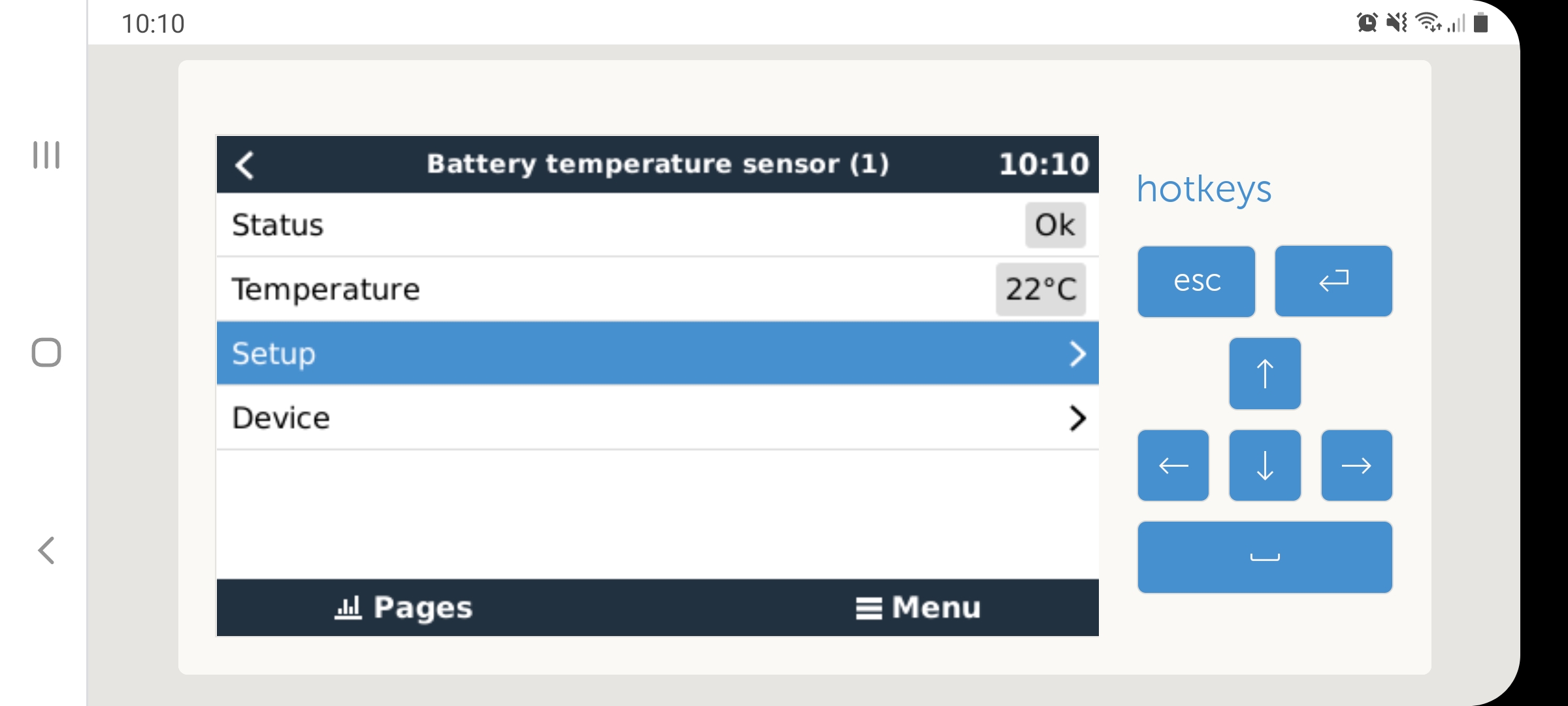
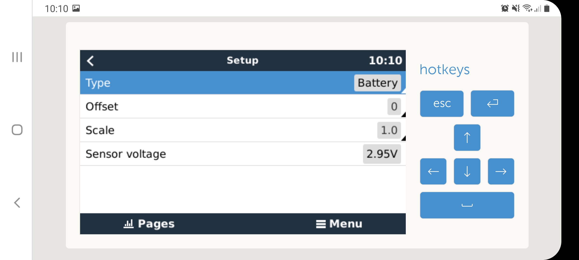
Then go into the temperature sensor > Setup.

screenshot-20210131-101032-chrome.jpg

Then correct the reading with an appropriate Offset and/or Scale factor. The sensor voltage as measured by the Venus OS is also reported there, which can be helpful with troubleshooting.

screenshot-20210131-101042-chrome.jpg


4 comments
2 |3000

Up to 8 attachments (including images) can be used with a maximum of 190.8 MiB each and 286.6 MiB total.

raymiller avatar image raymiller commented ·

Thanks for the solution, I did not know about this.

cheers

0 Likes 0 ·
kevgermany avatar image kevgermany ♦♦ commented ·
I've been trying to do this on a ccgx. Despite being in superuser, I cannot find the adjustment screen. How do I get to it? Or is it blocked in the ccgx?
0 Likes 0 ·
Show more comments
sunnycoastgreg avatar image
sunnycoastgreg answered ·

my question is similar to above .. however a little different my system has
victron skylla i 3 charger, with its supplied temp sensor fitted to the house battery (neg terminal)
Victron BMV 702 shunt, fitted with (correct) optional temp sensor to same house battery. (pos terminal)

i recall from somewhere that victron uses two different types of temp sensors, and i think im correct that the two sensors in above situation are different.

my challenge is that the two report quite different readings (both connected to same battery bank)

eg BMV reports 23.0 at same time as skylla 18.7C.. & a check with infrared temp gun shows 23.5C
( a good match to BMV shunts temp sensor) but VERY poor tomthe skylla.
And its the skylla sensor that is used for its temp/volt compensation calculation etc
My batteries are “only” AGM, so probably less critical than if i were using Lithiums.

Whilst i know i can adjust the BMv shunts temp .. it doesnt need it..
However the skylla does ...

and help, comments welcome...

2 |3000

Up to 8 attachments (including images) can be used with a maximum of 190.8 MiB each and 286.6 MiB total.

kevgermany avatar image
kevgermany answered ·

Thanks. I'm having a similar problem, the battery temp seems to be far too high. Easysolar with standard victron temp sensor on the negative terminal.

Am I right in saying, based on this thread, that the sensor is measuring the temperature of the battery terminal, and that there is an assumption that the terminal temp is the internal temp. Also that I can use an accuarte thermometer to measure the terminal temp and use that to correct the sensor inaccuracy using superuser mode?

Thanks in advance.

2 |3000

Up to 8 attachments (including images) can be used with a maximum of 190.8 MiB each and 286.6 MiB total.

martijnt avatar image
martijnt answered ·

Hi,

If I want to create an additional sensor, by connecting an LM335, can I simply use 2 wires from the Cerbo temp ports to the ML335?


10 comments
2 |3000

Up to 8 attachments (including images) can be used with a maximum of 190.8 MiB each and 286.6 MiB total.

kevgermany avatar image kevgermany ♦♦ commented ·
Unless you have reasonable electronics knowledge, no. Easier and quicker to get the Victron sensor.
0 Likes 0 ·
martijnt avatar image martijnt kevgermany ♦♦ commented ·
What else needs to be done then? Does it need a resistor? Something else? Additional calibration in the Cerbo?
0 Likes 0 ·
kevgermany avatar image kevgermany ♦♦ martijnt commented ·
The Cerbo takes up to 4 temp sensors. So there's obstacle number one. The LM335 needs specific wiring, has three connectors, possible calibration. If you have the knowledge and willingness to do the research, find the datasheet, work out the wiring, adapt this for the Cerbo installation... Then it should work.

If you want to do this, suggest you ask the question in the modifications space, someone there may be able/willing to help.


0 Likes 0 ·
alklecks avatar image alklecks kevgermany ♦♦ commented ·

@kevgermany, @martijnt

I was just looking into DIY building of a temp sensor for the Cerbo GX and found

a) the LM135 is electrically the more accurate version compared to the LM335 (-55..+150C instead of -40..+100C) and

b) works, if only the pins 2 and 3 of the LMx35 are connected to the inputs of the cerbo. Check out the data sheet here.

I isolated pin1 and put the whole sensor with the isolated cable connections into the steel tube and filled it with epoxy. Seems to show 2deg more than the real temp but with the superuser hack that can be easily adjusted...

So, all in all an easy build IMO.

datasheet: https://www.st.com/content/ccc/resource/technical/document/datasheet/04/fa/9d/16/39/87/44/8d/CD00000459.pdf/files/CD00000459.pdf/jcr:content/translations/en.CD00000459.pdf

2 Likes 2 ·
kevgermany avatar image kevgermany ♦♦ alklecks commented ·
Thanks, yes I'm well aware. This will solve calibration on some GX devices, but not the CCGX.
0 Likes 0 ·
martijnt avatar image martijnt alklecks commented ·

I figured the voltage from the temp-ports on the Cerbo was too high (from what I've found regarding this sensor and Arduino), but experimenting with a resistor showed a very very different temperature. Connected just the two wires and difference with the original Victron is 1 degree C. So, I think it's fine :)


0 Likes 0 ·
kevgermany avatar image kevgermany ♦♦ martijnt commented ·
Good. Mine over-read by 6C. I replaced it, error came down to about 1.5C
1 Like 1 ·
foreignerpv avatar image foreignerpv alklecks commented ·

hi kevgermany

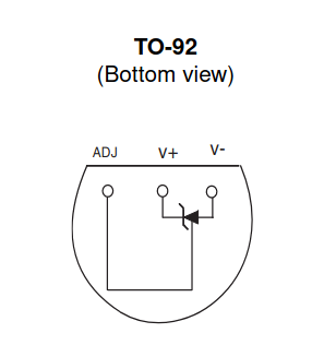
You describe to use pin 2 and pin 3.

Do you mean the following pins?

[2] ADJ

[3] V-bildschirmfoto-vom-2022-11-25-10-49-35.png


0 Likes 0 ·
foreignerpv avatar image foreignerpv foreignerpv commented ·

solution

LM335Z temperature sensor TO92

Correct pins to use are V- and V+

The resistance of these pins to each other is approx. 32 Kohm depending on the temperature in the area, regardless of the polarity of the multimeter.


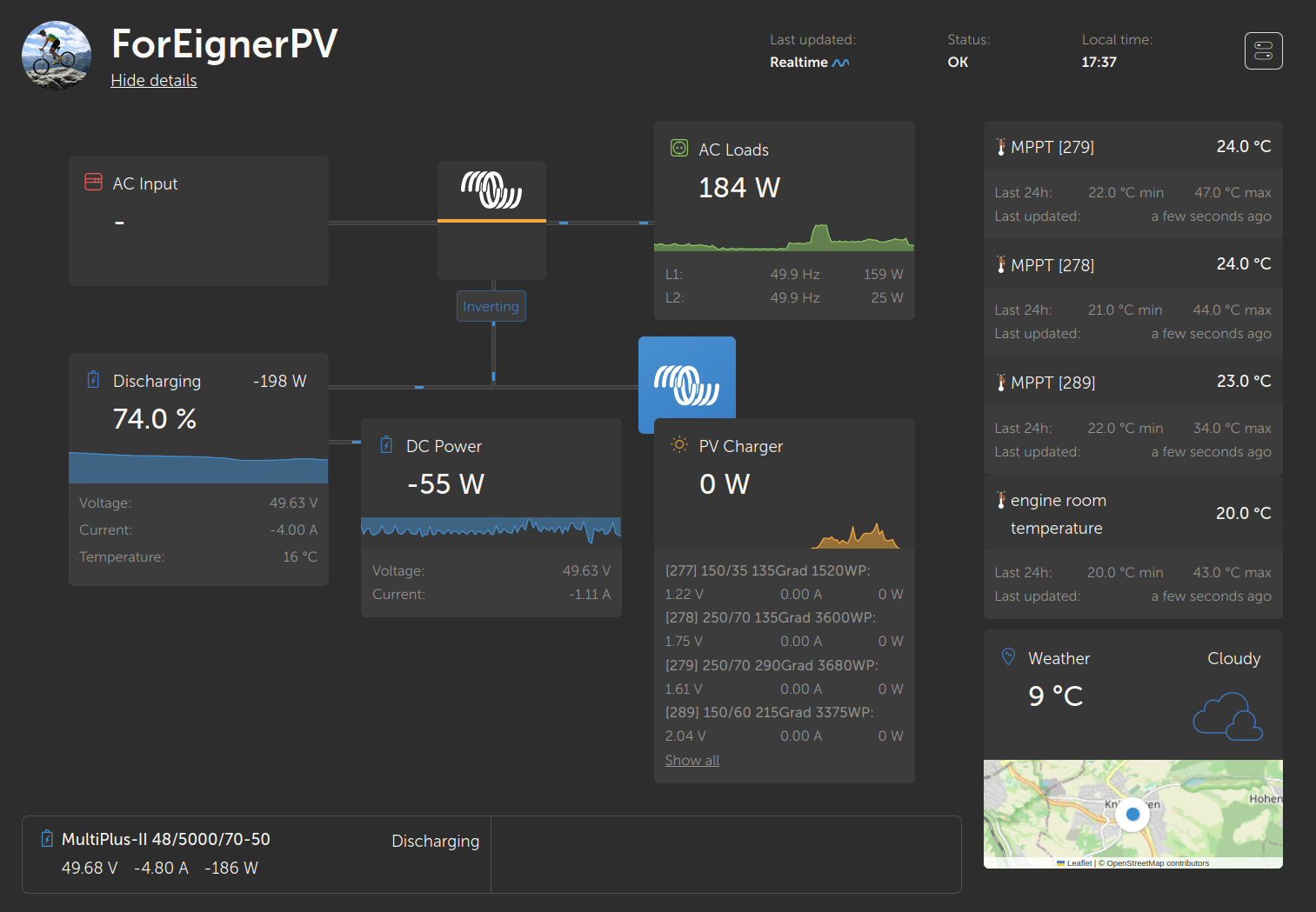
bildschirmfoto-vom-2022-11-25-17-37-09.pngbildschirmfoto-vom-2022-11-25-17-37-45.pngbildschirmfoto-vom-2022-11-25-17-06-33.pngImage Caption


1 Like 1 ·
martijnt avatar image martijnt kevgermany ♦♦ commented ·
Thanks, I'll look it up and search the other group.
0 Likes 0 ·