question

spudgun avatar image
spudgun asked

SmartSolar MPPT RS 450/100

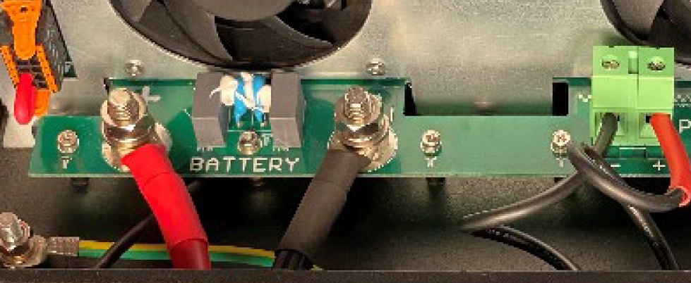
On the battery positive and negative terminals in the unit there are two nuts per terminal. Is the intention here to sandwich the M8 ring connector between the two nuts or should the M8 ring connector be placed directly onto the PCB contact and tightened down with the two nuts?

In the datasheet it looks like the M8 ring terminals are sandwiched between the two nuts as in the below image. Does having a nut below the M8 ring terminal not just introduce extra resistance in the circuit? Possibly very little resistance which may not be an issue. Maybe the idea here is that the two nuts offer more surface area for current to flow when the sandwich method is used. Anyone able to offer advice on the correct way to install the M8 ring terminals on this device?

smartsolar-mppt-rs-450-100.jpg

MPPT SmartSolar
2 |3000

Up to 8 attachments (including images) can be used with a maximum of 190.8 MiB each and 286.6 MiB total.

1 Answer
alan avatar image
alan answered ·


As you have stated, Having the nut there would increase surface area and therefore load capability, plus the nut provides a standoff to protect the PCB.

I have seen many different systems utilise this dual nut sandwich method, from huge Alu/nokia switches down to small DC rectifiers.

That's the way I would be going.

3 comments
2 |3000

Up to 8 attachments (including images) can be used with a maximum of 190.8 MiB each and 286.6 MiB total.

Ingo avatar image Ingo commented ·

Hmm... The skin effect is only present in AC and varies the depth of current penetration into the conductor core depending on frequency - the extreme being wave guides for RF being hollow. The higher the frequency the more it tends not to use the center of the conductor and flow on the 'outside skin' mostly. DC which doesn't have a alternating frequency component should use the whole conductor.

0 Likes 0 ·
Show more comments