This question may answer part of another question I posted two days ago.
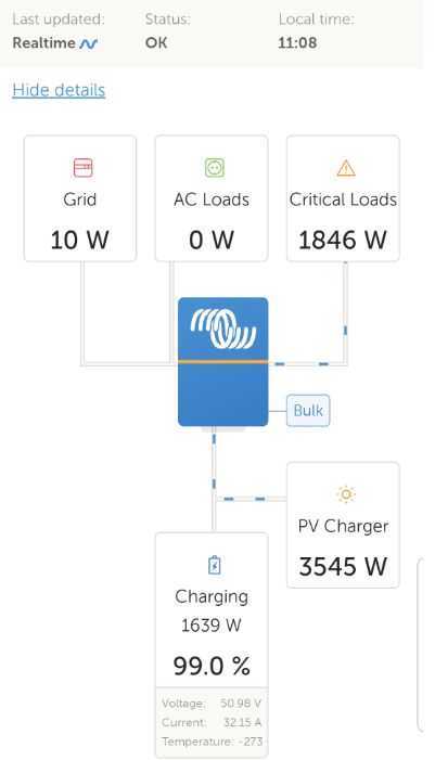
The VRM layout for the Multiplus 2 looks like the Screenshot document below
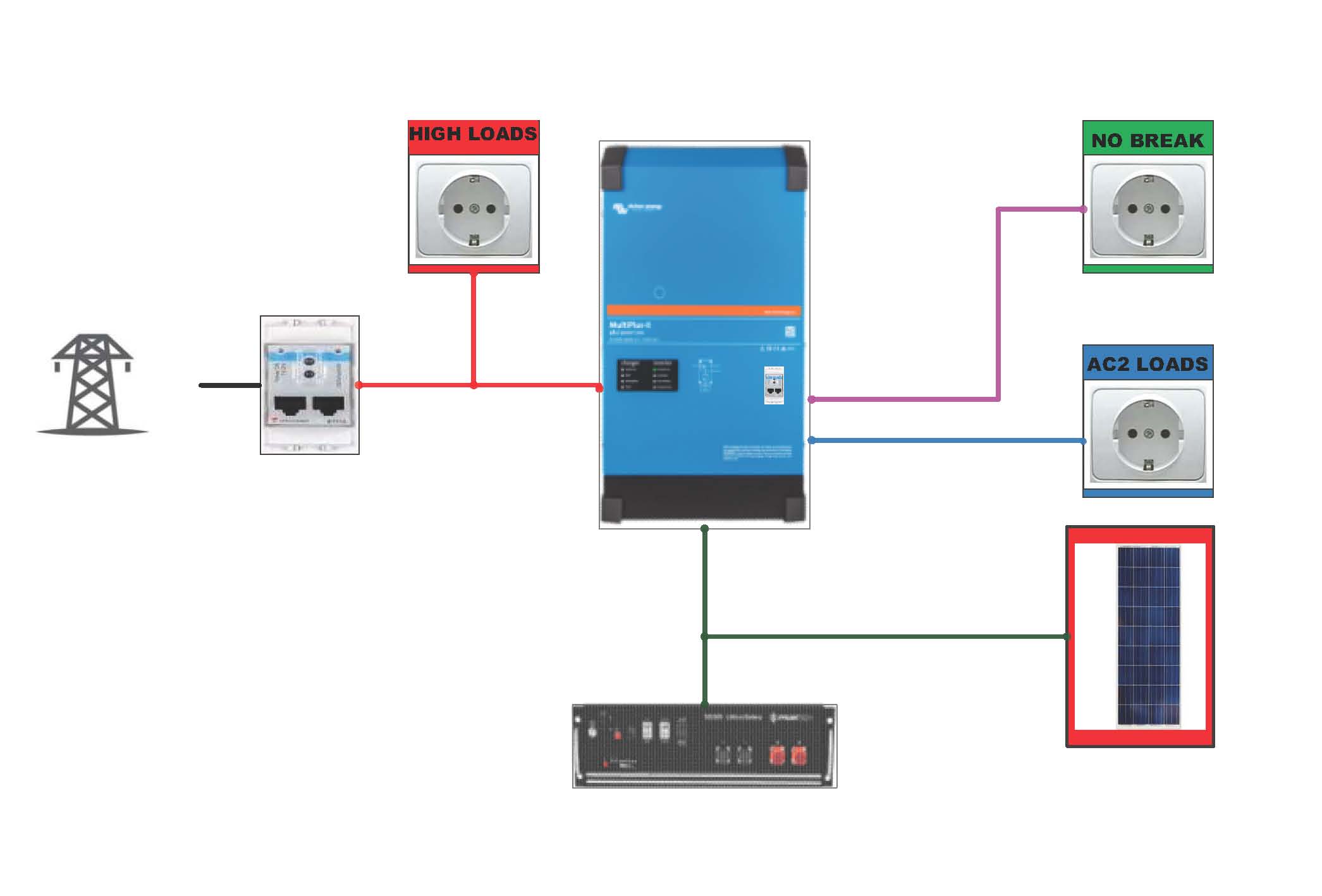
However, the second image reflects the actual layout
Surely the VRM portal (and remote console / Colour control) should rflect the actual statof the Multipluss wherein
AC1 = Critical loads (No break loads) - Green on image
AC2 = loads connected to AC2 of multiplus - Blue on image
"High loads" - Red load on Image
It is somewhat confusing as to what AC loads and Critical loads actually mean on the current VRM portal layout especially the "flow" of current depicted by the blue dashes.
Does "critical loads" (1846w for clarity) mean AC1 out and AC2 out
Does "AC loads" (0 w for clarity) mean the bidirectional load which is fedback into the grid but consumed by the "red" high loads?


