question

katoomrxc avatar image
katoomrxc asked

SmartSolar MPPT 100/50 Not Starting

I'm assembling my first Victron Energy system. The new SmartSolar MPPT 100/50 acts as though it's not seeing sufficient voltage to start charging. It flashes all three lights momentarily upon battery connection, then the 'Bulk' light (blue) flashes periodically every 3-4 seconds. No sign of Bluetooth for pairing using two different devices. Nothing changes upon connection of PV, though the voltage drops from the open circuit voltage (Voc - about 44 VDC) to near zero when the breaker is flipped. The controller is not heating up as though it was sinking the PV power (600 watts).

PV Configuration: Four (4) HQST-150D panels in a 2x2 configuration (24V nominal); expected voltage drop between array and controller will be around 1.2% at optimum voltage and current (Vmp=36; Imp=17A). Voc confirmed between the hot side of the breaker and PV- of the controller before closing the breaker.

DC Distribution: Midnite Solar breaker between the batteries and the MPPT 100/50 (battery on the '+' side of breaker) and another between the PV array and the controller (PV on the '+' side). Voc confirmed between the hot side of the breaker and PV- terminal of the controller before closing the breaker.

Power Storage: Four (4), large AGM batteries in parallel (12V nominal). Voltages are balanced and presently around 12.5 VDC with a 30 watt load being fed directly from the batteries.

Thanks for any suggestions you may provide!

MPPT Controllerssmart solar set-up help
2 |3000

Up to 8 attachments (including images) can be used with a maximum of 190.8 MiB each and 286.6 MiB total.

6 Answers
JohnC avatar image
JohnC answered ·

Hi Katoom. Reverse pv polarity would likely do that. Check it with a multimeter as close as you can to the mppt.

2 |3000

Up to 8 attachments (including images) can be used with a maximum of 190.8 MiB each and 286.6 MiB total.

katoomrxc avatar image
katoomrxc answered ·

Thanks for responding, JohnC. You got me thinking, including whether my multimeter leads were swapped. Unfortunately, that's not it. The negative side of the PV array is definitely in the PV- terminal of the controller directly from the building bulkhead entrance. The positive side runs directly (18-24") to a breaker and then another 12-15" to the controller. Same situation today: Voc between the hot side of the breaker and controller PV- at the breaker until it's closed, then 0.2 VDC between both sides both at the bulkhead entrance and between controller PV+ and PV-.


I'm going to bypass the breaker tonight and see what happens tomorrow. 600w shorted at the breaker ought to be showing some signs, though - like smoke!
2 |3000

Up to 8 attachments (including images) can be used with a maximum of 190.8 MiB each and 286.6 MiB total.

Guy Stewart (Victron Community Manager) avatar image
Guy Stewart (Victron Community Manager) answered ·

Can you please take some photos?

You should be able to see the MPPT in VictronConnect from the battery voltage connection regardless of the PV.

2 |3000

Up to 8 attachments (including images) can be used with a maximum of 190.8 MiB each and 286.6 MiB total.

katoomrxc avatar image
katoomrxc answered ·

I just tried a Bluetooth scan from a Windows computer nearby. No show.

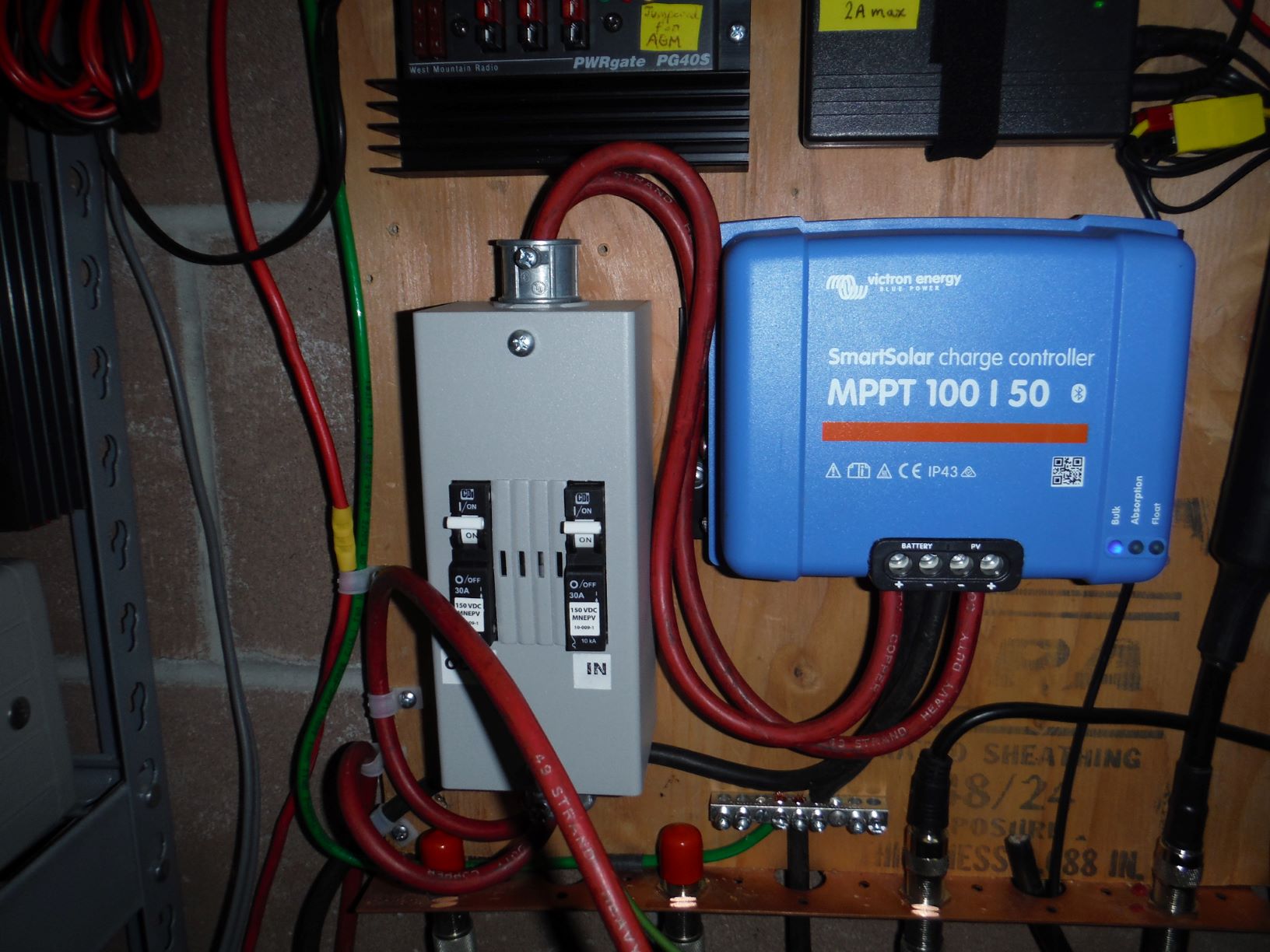
First photo is of controller and breaker box. I managed to catch the blue flash. "IN" breaker is connected between the PV bulkhead entrance and controller. Red wire in the foreground is from the "OUT" breaker to the battery. Battery, "Battery -", and load negative are connected at the bus bar.

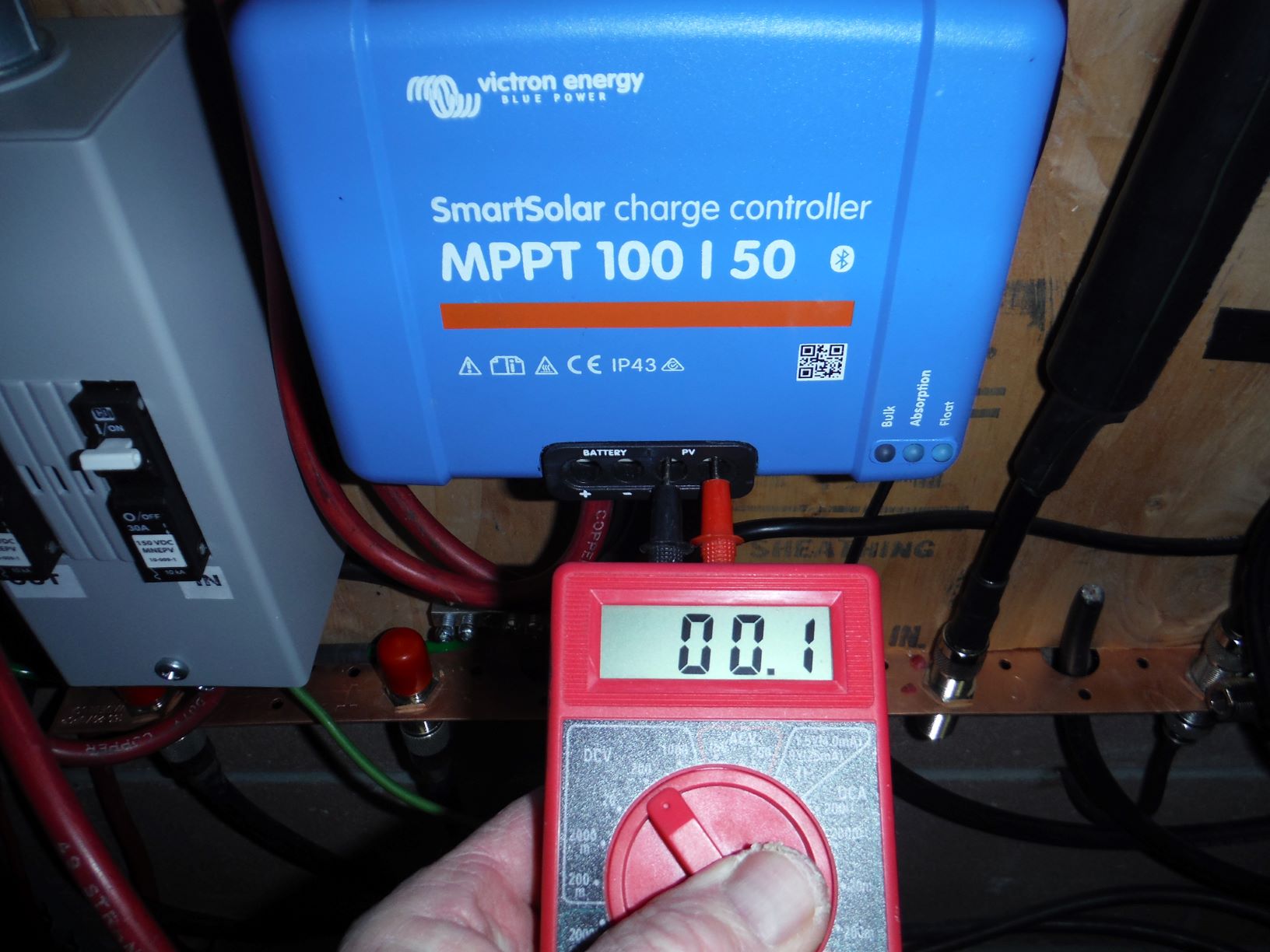
Second photo below is showing voltage reading at the PV terminals with breaker closed (breaker nearest to the controller).

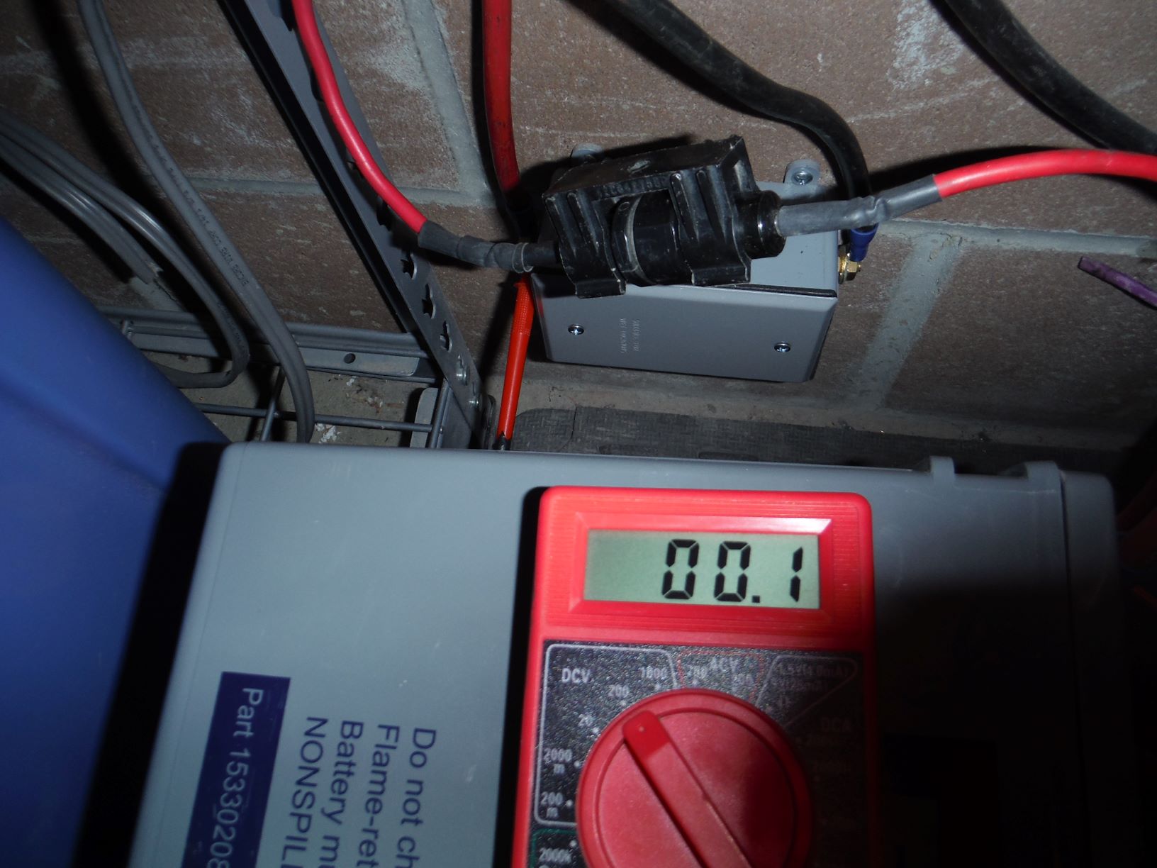
Third photo below is showing the same reading with positive lead at the bulkhead entrance; negative lead (not shown) is still at the controller PV- terminal. The big fuse in the foreground goes to the load. Sorry for the clutter; it's behind the batteries.

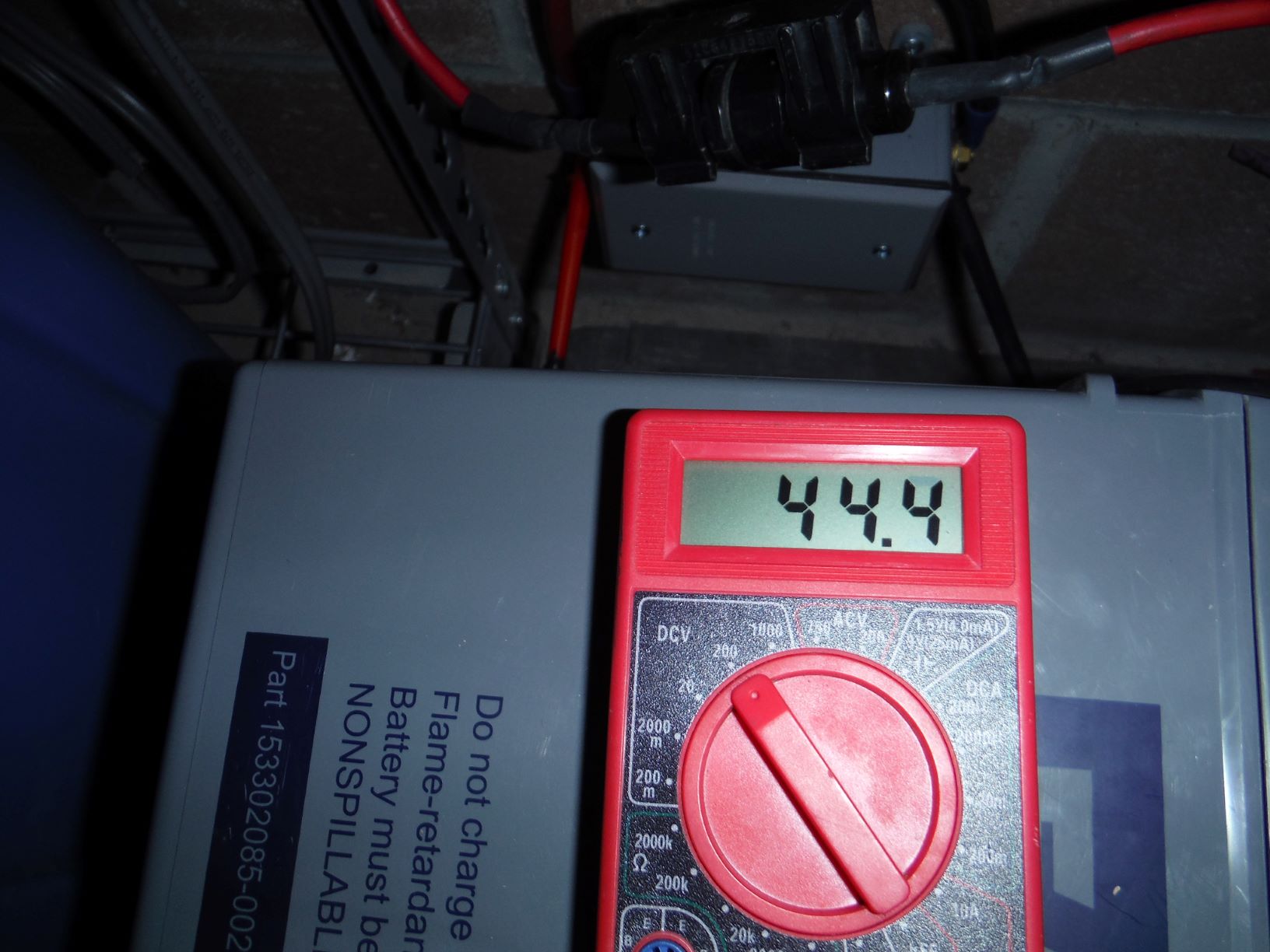
Finally photo below is with PV breaker open, multimeter leads at the bulkhead entrance. Same voltage show at the breaker (hot side).


dscf2314m.jpg (236.7 KiB)
dscf2298m.jpg (193.2 KiB)
dscf2297m.jpg (200.1 KiB)
dscf2295m.jpg (191.6 KiB)
2 |3000

Up to 8 attachments (including images) can be used with a maximum of 190.8 MiB each and 286.6 MiB total.

brokenlegg avatar image
brokenlegg answered ·

Hi, I’m actually having the exact same issue with one of my 150/70 MPPT controllers, randomly after a year of seamless operation. The other controller I have in parallel is working fine. I noticed that the resistance between the input on the good controller is around 1Mohm, whereas the resistance on the faulty one is about 4ohms.
I’m not sure what this means, but it seems like something internal may have shorted out. I haven’t got to the bottom of it yet, but I’ll let you know if I figure anything more out.

2 |3000

Up to 8 attachments (including images) can be used with a maximum of 190.8 MiB each and 286.6 MiB total.

Justin Cook avatar image
Justin Cook answered ·

@KatoomRXC, it's worth noting that a Windows computer cannot connect with a Smart anything over BT... in a very simplified explanation, the laptop/desktop BT protocols are different than the mobile BT protocols used by Victron Smart devices. BT connection to these devices is only possible using a smartphone or tablet.

To connect to the device on a computer, you will need the VE.Direct to USB Interface... but that should be unnecessary as long as you have your phone or tablet handy.

2 |3000

Up to 8 attachments (including images) can be used with a maximum of 190.8 MiB each and 286.6 MiB total.

Related Resources

Additional resources still need to be added for this topic