question

Jmarc avatar image
Jmarc asked

DVCC, BMS and Ve.Bus interaction

Hi,

I have been working on a couple of project involving MG batteries with BMS, Quattro and CCGX controller. I have read the DVCC section of the CCGX manual and if it greatly help understand the basis of DVCC some details are left out and I need to reassure our customers.

Some system also includes Blue Solar Ve.Can controller(150/85), Skylla and /or Skylla-i

System are set per recommended settings in the DVCC section of the manual.

The Manual mentions that when DVCC is ON the Ve.Bus device and MPPT system are "controlled by the BMS". and they follow the CVL, CCL and DCL sent by the BMS.

Q1) The BMS does not send the data to the device directly since they are not on the same network. The CCGX appear to be redirecting the references. Are each device directly controlling the charge voltage based on the CVL or is the CCGX adjusting the Current limit to each device to meet the CVL?

Q2) In a case of the BMS controlled system, is there a need to set Absorbtion/Float voltage or are those numbers ignored by the Device?

The Solar charger strictly indicate external control and if the BMS communication is lost they seem to Stop charging. So it seems that the setting are ignored. Are they?

The Case of the VeBus device is not that obvious. External control state does not exist. It seems that the LED are either Bulk when some charging is happening and Absorbtion when the charging stops or oscillates. Never seems to get to float which is disconcerting for some of our client.
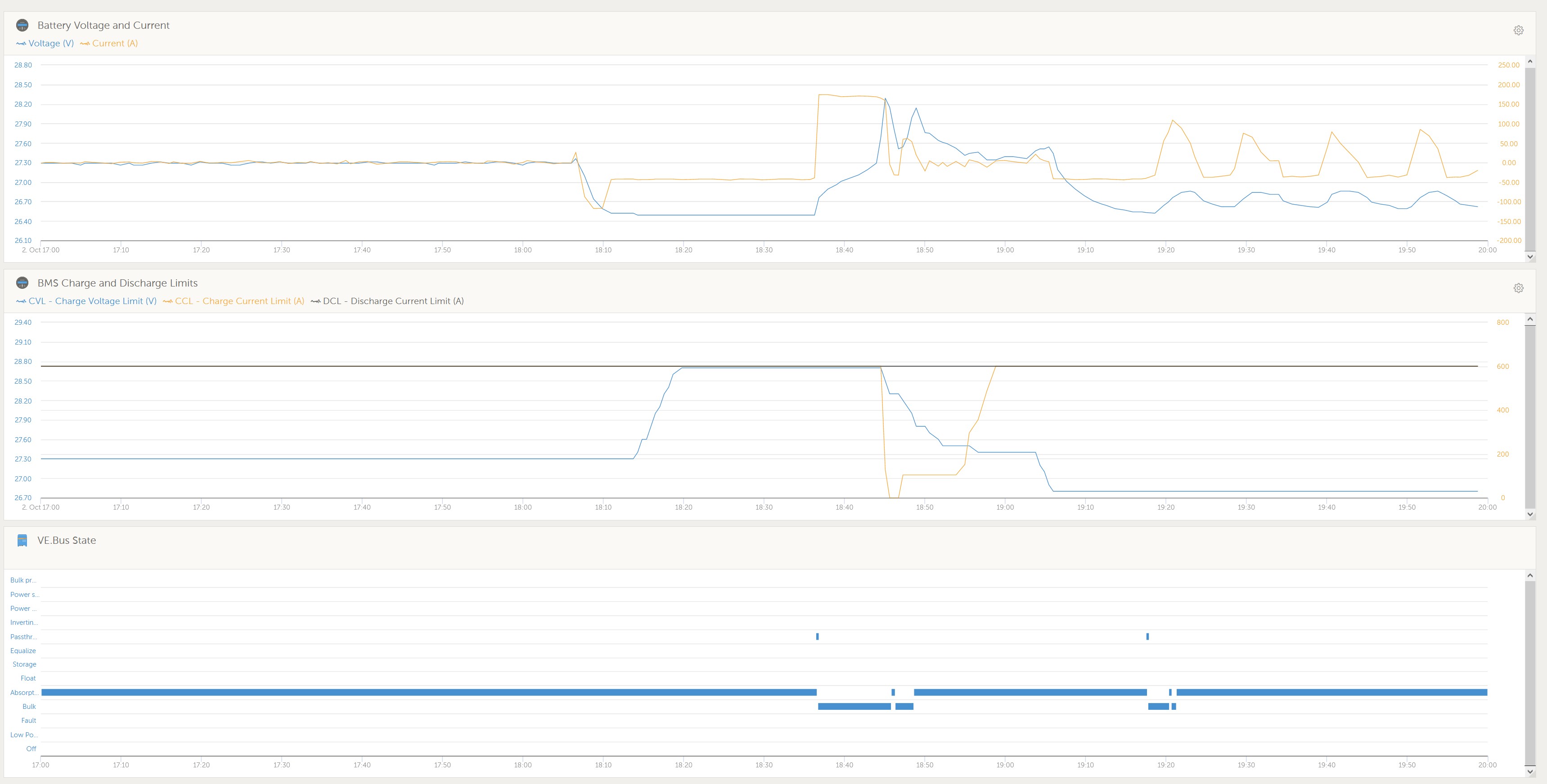
Is this the intended behavior?

Is the absorption voltages set in the charger profile totally ignored or used as "Limits"?

Should the BMS communication stop how will the system react? Will the Quattro stop charging or inverting?


MPPT ControllersMultiPlus Quattro Inverter ChargerDVCC
2 |3000

Up to 8 attachments (including images) can be used with a maximum of 190.8 MiB each and 286.6 MiB total.

2 Answers
Daniël Boekel (Victron Energy Staff) avatar image
Daniël Boekel (Victron Energy Staff) answered ·

Hi @Jmarc@aeandmengineering.com

The answers should be in the manuals:

Q1: when DVCC is 'on' the battery controls charge / discharge limits, read the manual on DVCC for details.

https://www.victronenergy.com/live/ccgx:start#dvcc_effects_on_the_charge_algorithm

Q2: generally you set this at a safe level.

https://www.victronenergy.com/live/battery_compatibility:mgenergysystems


Q1) The BMS does not send the data to the device directly since they are not on the same network. The CCGX appear to be redirecting the references. Are each device directly controlling the charge voltage based on the CVL or is the CCGX adjusting the Current limit to each device to meet the CVL?

Q2) In a case of the BMS controlled system, is there a need to set Absorbtion/Float voltage or are those numbers ignored by the Device?

2 |3000

Up to 8 attachments (including images) can be used with a maximum of 190.8 MiB each and 286.6 MiB total.

valentin-silvera avatar image
valentin-silvera answered ·

Hi @Daniël Boekel (Victron Energy Staff)

Taking advantage of the question here, I would like to clarify a doubt. Why is it that in a system that has a GX controller and battery with compatible BMS, the DC voltage to charge the battery is not automatically adjusted to the CVL reference value by correcting the voltage loss value through the cables?
I understand that some accessories are needed for this, but the GX controller is already receiving the voltage value measured by the BMS and also how much voltage the inverter or MPPT is generating. In other words, it has all the information to make a voltage loop and correct the value so that the CVL reaches the battery terminal exactly.

2 |3000

Up to 8 attachments (including images) can be used with a maximum of 190.8 MiB each and 286.6 MiB total.