Hi everyone,
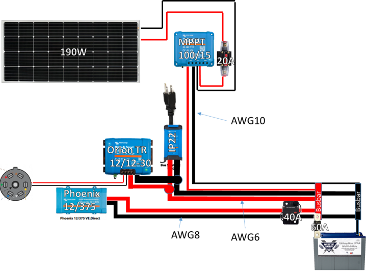
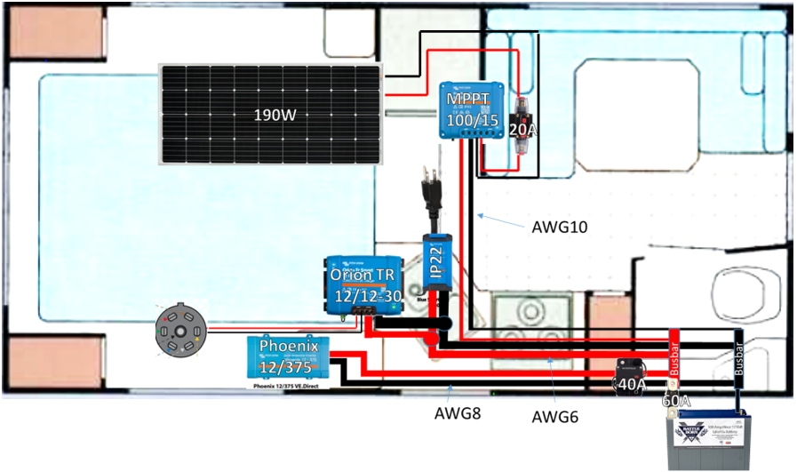
I'm setting up a solar system for my cabover camper, and I have a few questions about setting up the solar system in the camper, primarily regarding the wiring and fusing of the system. I have the following components:
- 190W Rich Solar panel
- Victron MPPT 100/15 charge controller
- IP22 charger for charging when on shore power
- Victron Orion TR 12/12-30 DC-to-DC converter for charging from the truck alternator
- 12V, 100Ah Battleborn LiFePO4 battery
- Victron Phoenix 12/375 DC-AC Inverter
- Victron Bluetooth smart battery sense (not shown in the schematics)
The devices that will be powered from this system are:
- From the inverter: only oxygen generator (rated at 100W)
- From 12V DC :
- Lights
- Water pump
- Fan/pilot for the gas heater
- Pilot for the gas fridge (maybe the fridge itself, not sure what is the consumption)
- All alarms (gas, fire, CO)
- AC will only be powered when on shore power.
I'm planning to install positive and negative busbars in the battery compartment and connect the positive from the battery to the busbar using 60A MEGA fuse and AWG6 wire. The solar panel input to MPPT will be fused with 20A inline circuit breaker, and all wires are AWG10. The inverter will be fused with a 40A circuit breaker on AWG8 wire. A few questions that I have for the esteemed members of the community are:
- Should the inputs from IP22 and Orion TR to the battery also be fused? Both put out 30A charging current, if they do, I assume 40A fuse would work?
- Is 60A MEGA fuse for the battery positive terminal too small? Looking at the inverter, it is rated for 375W which divided by 12V is 31.25A, but the manual says that it can support peak 700W, which is almost 60A, so both the inverter and battery fuse may be undersized in the schematics.
- I planned to connect OrionTR and IP22 at a location close to where the 7-pin cable comes into the camper. Can MPPT output be connected to the same place, or should it go on the busbar close to the battery? My logic is that I will either charge the battery from the shore power, or from the truck, but never from both at the same time. Solar on the other hand will charge continuously during the day, so I would have two charging sources, which also brings up a question if AWG6 cable should be thicker and if they need to be fused should the fuse take into account maximum output of IP22/Orion and MPPT (45amps)?
- Anything else that I'm missing/have overlooked?
I would really appreciate all your suggestions/corrections to help me connect all of the components!
-Darko


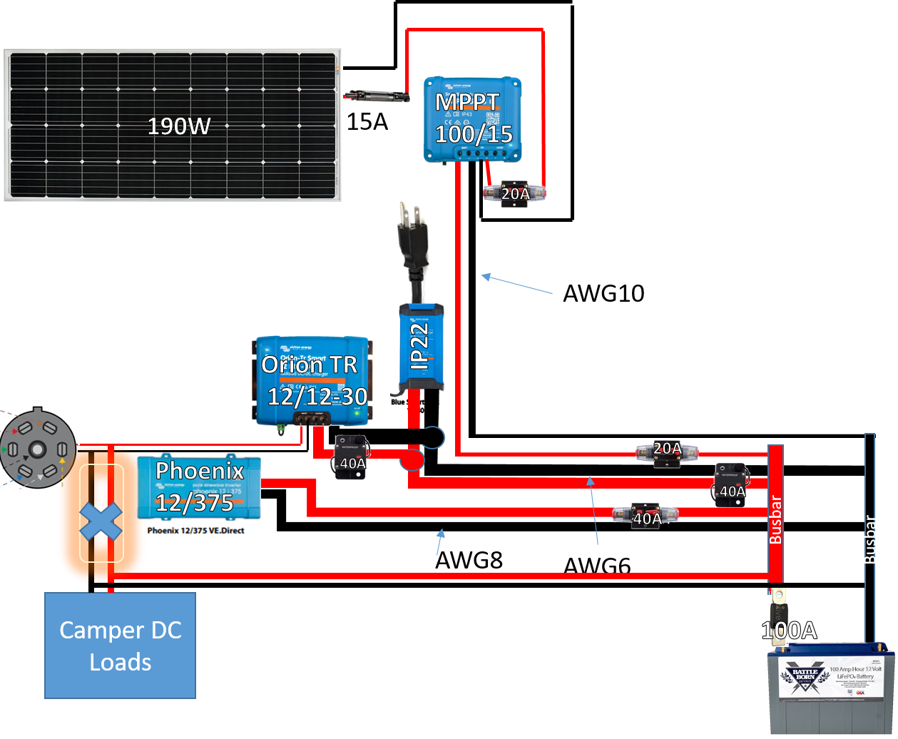
 A follow up question: I started assembling the whole system, and updated the schematics, because I realized I didn't include DC loads that are going to be connected in the camper: I realized one thing: If I connect the Orion TR DC to DC to my truck 7-pin plug while my camper DC is also connected to the truck 7-pin then the input and output voltage will be set by Orion, I think? I think I need to break direct connection between the truck 7-pin and the camper fuse box, so that the input voltage to Orion is whatever the truck is putting out, and that the output voltage to the battery and the camper DC distribution is set by the Orion/battery. I highlighted the problematic connection in the updated schematics. Is my assumption correct?Also, should I separate the positive busbars between the charging devices (Smart Solar, Orion, IP22) and the devices that use DC (Camper loads and Phoenix inverter)? I saw that Victron in their schematics has a switch to turn off loads, e.g.