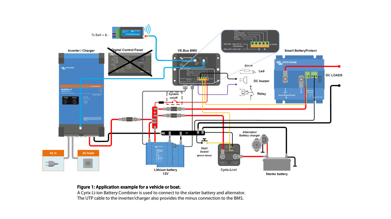
Replace the Digital Control Panel with a VE.Bus Smart dongle.
Figure 1 of the Victron PDF . System Layout below
https://www.victronenergy.com.au/upload/documents/Datasheet-VE-Bus-BMS-EN.pdf
Will this work ?
Any help would be great.

This site is now in read-only archive mode. Please move all discussion, and create a new account at the new Victron Community site.
Replace the Digital Control Panel with a VE.Bus Smart dongle.
Figure 1 of the Victron PDF . System Layout below
https://www.victronenergy.com.au/upload/documents/Datasheet-VE-Bus-BMS-EN.pdf
Will this work ?
Any help would be great.

Some features of the VE.Bus Smart Dongle work in this configuration, but others do not.
When the VE.Bus BMS is connected, you cannot control the current limit, or On/Off/Charger control via the VE.Bus Smart Dongle in VictronConnect.
More info here - https://www.victronenergy.com/live/vebus_smart_dongle_manual
With the latest update of the smart dongle firmware and victron connect app, it is actually possible to control the AC input current limit. Yet it is still not possible to turn off and on the multiplus inverter.
Please Victron guys, add this option, will make us all without space for digital control panel very happy…
thanks,
Martin
I think the last question that I haven't found is if the smart dongle is supposed to be plugged into the BMS or if it should be plugged into the inverter in this scenario. From everything I've read, it seems that the Smart Dongle should be plugged directly into the inverter rather than the way you have it drawn.
Of course, with the V2 BMS, all of the features work well and the documentation is better, but for someone who already has the V1....
The V2 is definitely better...
Additional resources still need to be added for this topic
28 People are following this question.