question

kazim avatar image
kazim asked

Need Schematic software

I asked Victron community for schematic for my expedition vehicle. However, I didn't get positive feedback and I am going to draw myself. I was wondering if Victron does provide a software that I can select products and do schematic .

if it does, how can I get it?

software
2 |3000

Up to 8 attachments (including images) can be used with a maximum of 190.8 MiB each and 286.6 MiB total.

8 Answers
Justin Cook avatar image
Justin Cook answered ·

@Kazim, no, Victron does not provide schematic development software; there are a plethora of free programs available, however, if you do not wish to pay for the (rather exorbitant) cost of Microsoft Visio, which is the professional solution.

A quick Google search will render plenty of results; personally I'd suggest looking at Draw.io as many people are using that with ease for basic schematics or -with some time spent creating a product library and truly learning the ins and outs of it- even much more complex schematics.

3 comments
2 |3000

Up to 8 attachments (including images) can be used with a maximum of 190.8 MiB each and 286.6 MiB total.

kazim avatar image kazim commented ·

many thanks Justin. I do have aa professional Microsoft Visio. Does Victron products library available for the Visio use?

0 Likes 0 ·
Justin Cook avatar image Justin Cook ♦♦ kazim commented ·

@Kazim, unfortunately not, though it has been being discussed for a long time. Currently, however, an official Victron library is not available, due to the very high risk of 3rd parties generating incorrect schematics that appear to be Victron-approved.

Personally, I've always just downloaded the high-quality photos Victron makes available for every product and, with a quick resize, inserted them into my schematics.

1 Like 1 ·
kazim avatar image kazim Justin Cook ♦♦ commented ·

Many thanks, Justin for repsond

0 Likes 0 ·
ruben avatar image
ruben answered ·

Hi guys,


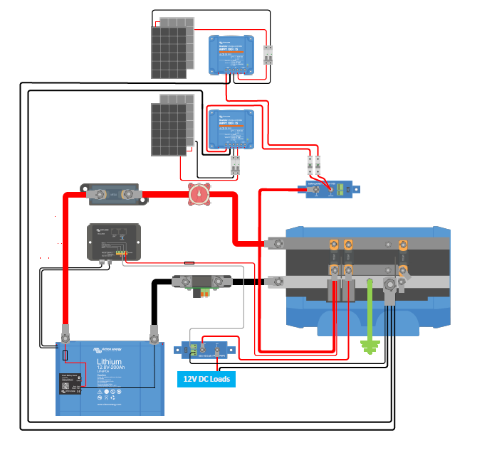
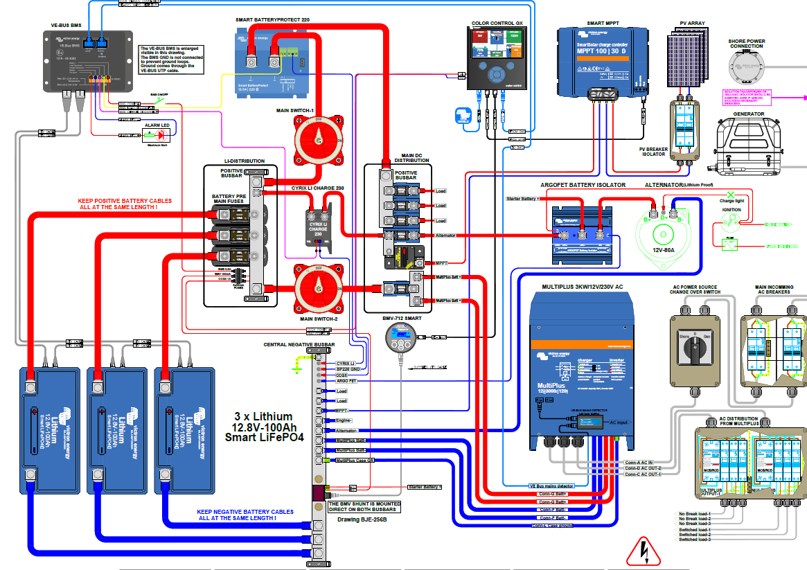
I would also like to create electrical schematics for myself and my clients as well. As images makes things often much easier to understand (for many people), I am curious how below schematics are made (see pics below, some random examples I found on this platform and also from Victrons download section).

I do understand that we should use a certain kind of design-program to make electrical drawings. But It seems that many designs do have similar design style (I do like the kind of cabling which even includes the cable lugs etc..., as in examples below). Assuming there actually exist a kind of library? Or might this library not be for open-use, and is it a kind of VICTRON internal library?! who knows more about this. And with which Software are below examples made?


Looking forward for any comment :)

Thanks,

Ruben

dc-lucians-van-2.png


ve-bus-bms-example.png


8 comments
2 |3000

Up to 8 attachments (including images) can be used with a maximum of 190.8 MiB each and 286.6 MiB total.

bathnm avatar image bathnm commented ·

I believe the above diagrams are formal Victron diagrams. Has anyone noticed the inaccuracy within the ve-bus-bms-example.png file. If it is not an inaccurate drawing then some other documentation on Victron sites is out of date. I believe the Colour Control is connected to the VE.Bus BMS incorrectly.

@Guy Stewart (Victron Community Manager) Can you confirm if the diagram is in fact correct or incorrect.

0 Likes 0 ·
ruben avatar image ruben bathnm commented ·

Hi @Bathnm,


thanks for replying. I guess so too that these diagrams are official Victron diagrams. Still curious how they create them (e.g. with which software) :)

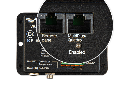
Actually I did not verify the full designs of the diagram. But if I have a quick look on the connector outputs of the VE-BUS bms, does is look quit OK connected, doesn´t it? (I don´t have experience with this device myself).

1604846054713.png

0 Likes 0 ·
1604846054713.png (273.0 KiB)
bathnm avatar image bathnm ruben commented ·

The only device that should or can be connected to the remote port is the DMC (Digital Multi Control). The Cerbo should be connected to the MultiPlus/Quattro port.

Check BMS manual and check the schematics listed under VE.Bus BMS

0 Likes 0 ·
bathnm avatar image bathnm bathnm commented ·

@Guy Stewart (Victron Community Manager), Are you able to confirm if the schematic in this thread is an actual Victron schematic and it is valid? Many Thanks

0 Likes 0 ·

Hi @Ruben and @Bathnm,

I made the top diagram (dc-lucians-van) in Visio using Victron's internal assets for the Victron Van project.

The ve-bus-bms-example was made in AutoCAD by Peter Bakker, a professional system designer. His diagrams are available at this page - https://www.victronenergy.com/support-and-downloads/systems#item=system-initial

We both exchange diagrams to each other before releasing them, to try and catch any mistakes, but they do occasionally slip through.

EDITED - The diagram linked above was incorrect, and is out of date. It has already been updated - here.. The manual is correct.

0 Likes 0 ·
ruben avatar image ruben Guy Stewart (Victron Community Manager) ♦♦ commented ·

thanks for your reply and the links.

Ruben

0 Likes 0 ·

@Ruben, @Bathnm,

Where did you get that diagram from?

It is out of date, and has been updated.

Here is the current correct version;

https://www.victronenergy.com/upload/documents/VE-Bus-BMS-example-with-3KW-12V-MultiPlus-230-Volt-revision-B.pdf

0 Likes 0 ·
bathnm avatar image bathnm Guy Stewart (Victron Community Manager) ♦♦ commented ·

@Guy Stewart (Victron Community Manager), I have never come across it on the Victron schematics, but seen it multiple times posted in these forums.

Thank you for confirming.

0 Likes 0 ·
yann avatar image
yann answered ·

hi

you can have a look at "qelectrotech" an opensource schematic editor that allow drawing of custom symbols, so you can get victron products images and turn then to schematic symbols to produce something that looks like the original victron schematics

www.qelectrotech.org

here is something produced with it : https://download.tuxfamily.org/qet/schemas_pdf/tableaulegrand.pdf

2 |3000

Up to 8 attachments (including images) can be used with a maximum of 190.8 MiB each and 286.6 MiB total.

dion-patelis avatar image
dion-patelis answered ·

It appears that LibreCAD.org and 'LibreOffice Draw' appear to do well using images from the downloads section in the Victron website. You will have to convert the images to .png and make the backgrounds transparent in order to route the wires to the terminals neatly.

Example from LibreCAD 20211205_1058_librecad.png

Examples from LibreOffice Draw:

20211205_1018_victron_drawings_using_libreoffice_draw.pdf

20211206_1641_vagabond_wiring.odg - good enough for quick rough physical mock ups.

To add points to the images which wires (connectors) can be attached to, use the - View --> Toolbars --> Glue Points - menus

then

'Show Glue Points Functions' icon --> 'Insert Glue Point' icon.

The 20211210_1553_vagabond_wiring.pdf files shows the output of the .odg file above.

For 3D wiring it seems there may be potential for freeCAD.org as the Victron .stp files import easily. Possibly O.K. for small 3D wiring presentations by using a B-spline and doing a 3D sweep. Not exactly the automatic 3D wire routing of AutoDesk Inventor, but then again you can open your files years later because you own the software and the files you created.


2 |3000

Up to 8 attachments (including images) can be used with a maximum of 190.8 MiB each and 286.6 MiB total.

neoneddy avatar image
neoneddy answered ·

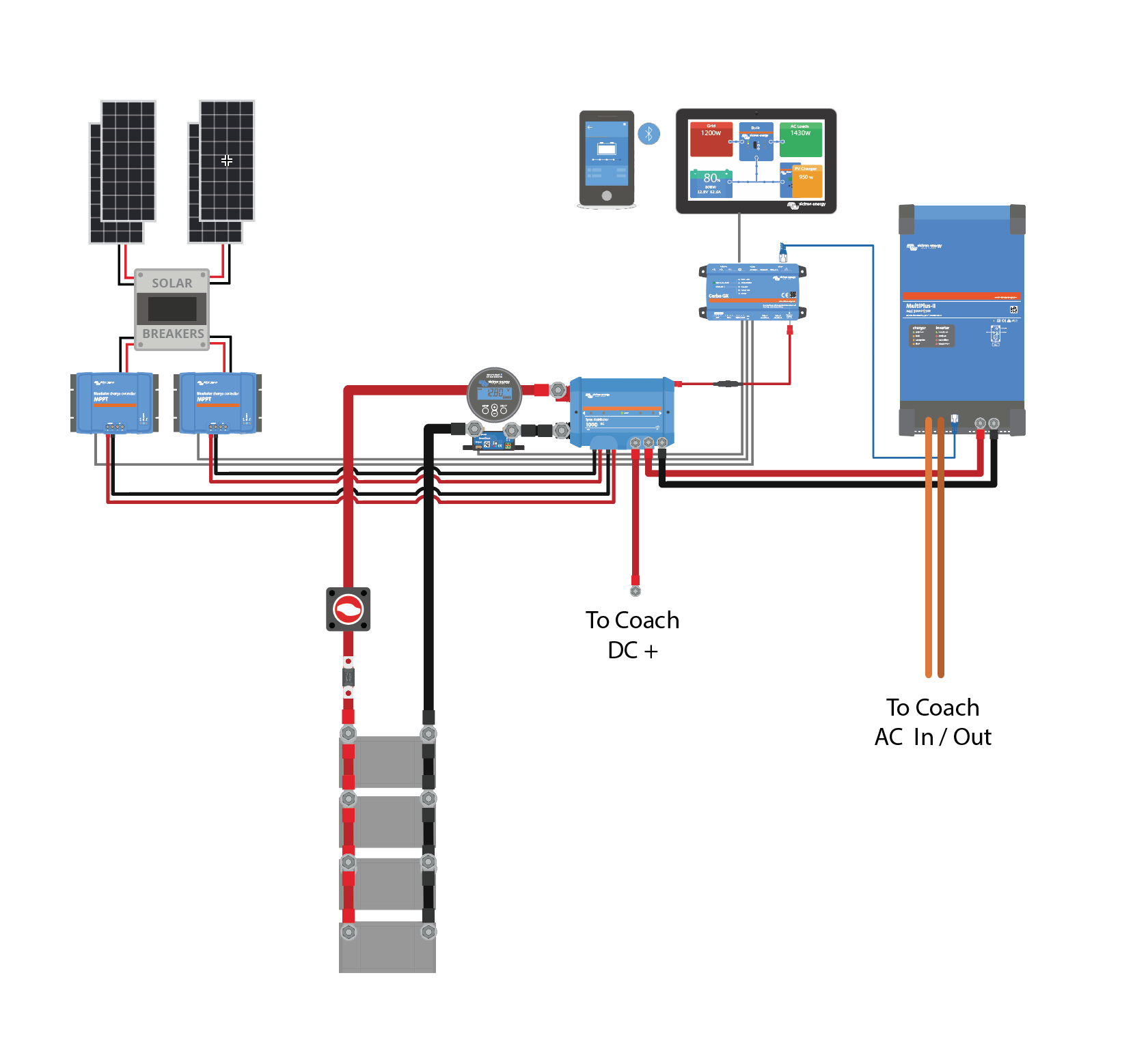
I'm a graphic designer among other things, so I'm familiar with Adobe Illustrator and it's tools. I have a feeling most of Victron's official drawings were done using this tool. I've been working on reverse engineering their component and wiring library to where I can quick drop components and draw lines and then select a cable size / color etc as a brush stroke. Below is an example I made for a client recently. https://sotasolar.com/blog/victron-wiring-diagram-template-illustrator-file Here is a link to where I'm publishing changes and so on. If you make or build new vector objects, please share back to shawn@sotasolar.com


1651407789158.png


1651407789158.png (186.9 KiB)
2 |3000

Up to 8 attachments (including images) can be used with a maximum of 190.8 MiB each and 286.6 MiB total.

schematic-steve avatar image
schematic-steve answered ·

@Guy Stewart (Victron Community Manager)

I operate a small family owned 2 employee autocad based drawing company in the UK. The Victron equipment is very popular in UK and I get enquiries from customers wanting the realism of your Victron schematics. Is it allowable for me to use picture information from Victron website in creating drawings, or should I just stick to schematic representations of the equipment?

2 comments
2 |3000

Up to 8 attachments (including images) can be used with a maximum of 190.8 MiB each and 286.6 MiB total.

Hi @Schematic Steve,

It's ok to use the Victron resources available.

The main concern that we have is if diagrams are confused as being official Victron diagrams, and especially if they contain a mistake.

As long as your diagrams are clearly marked with your own companies credentials as the author so there is no confusion that it might be official, then feel free to use the assets you can find.

0 Likes 0 ·
schematic-steve avatar image schematic-steve Guy Stewart (Victron Community Manager) ♦♦ commented ·
0 Likes 0 ·
greatlake avatar image
greatlake answered ·

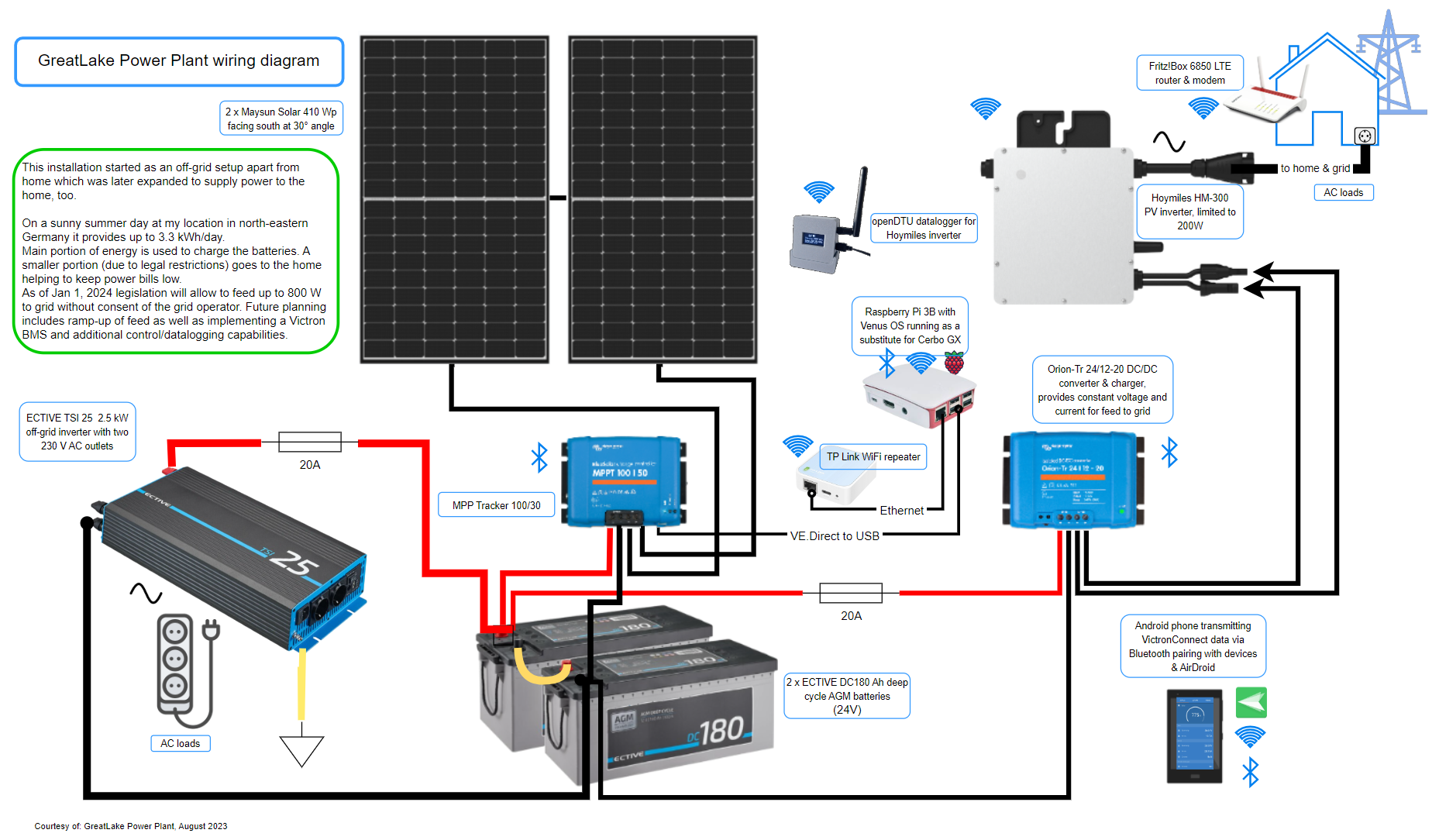
I did this example using draw.io after reading the thread. Their web editor should get two thumbs up, especially for the feature to move the wiring connection points of an image to the actual point where the cable should hook up to.
My drawing is work in progress. So use with discretion, please.

Best regards,
GreatLake
greatlake-wiring-diagram.png


2 comments
2 |3000

Up to 8 attachments (including images) can be used with a maximum of 190.8 MiB each and 286.6 MiB total.

nickdb avatar image nickdb ♦♦ commented ·

With respect, this is a bit of a dog's breakfast. Not really how PV inverters should be used, they expect to be connected to a solar panel and not a DC power supply.

I would encourage you to follow more of a best-practice approach as this could end in disappointment.

1 Like 1 ·
Show more comments
k-k avatar image
k-k answered ·

Use a victron inverter with ve.bus and connect to the cerbo.

2 |3000

Up to 8 attachments (including images) can be used with a maximum of 190.8 MiB each and 286.6 MiB total.

Related Resources

Additional resources still need to be added for this topic