question

machined avatar image
machined asked

Cerbo inputs for Dummies - Digital Inputs, Relays, Temperature Sensor, Pump, etc

Hello Everyone,

I just got a Cerbo up and running and the thing is so fun and I can't stop wanting to hook up things to it. The problem is I dont really know enough about things to feel confident in hooking everything up. I have read a lot of posts about digital inputs and sensors and it seems like they either arent answered or the answers are rocket science. So I'm hoping this post will be a dummies guide to everything. We all have these questions and so lets all make a resource thats easy to understand.

I currently have 3 MPPT systems, 150/70, 100/50 and 100/30, connected via VE Direct and a BMV-712 connected via VE Direct to USB.

I added a GPS via USB, GlobalSat BU-353-S4 USB GPS Receiver and that was plug and play and showed right up.

I've ordered three Victron temperature sensors, Victron Energy ASS000001000 Temperature sensor QUA/PMP/Venus GX. I'll be using one for the battery, one for room temp and one for outside temp. Those look to be plug and play but get mixed reviews. Does anyone know what other temperature sensors could used instead of the Victron? Are there better ways to get room and outside temp? Can I extend the temperature sensor leads by soldering on longer wire? Will that kill whatever resistance or whatever its using to get the signal.

I've also researched tank level sensors and the only ones I can find are the resistive level senders that mount from the top of the tank. I ordered a KUS Boat Fuel/Water level Tank sensor for the water tank and a Kus Boat Black Water Level Sensor / Holding Tank Sending for the grey tank. Are there any better options that you guys have found? There doesnt seem to be much out there for resistive sensors.

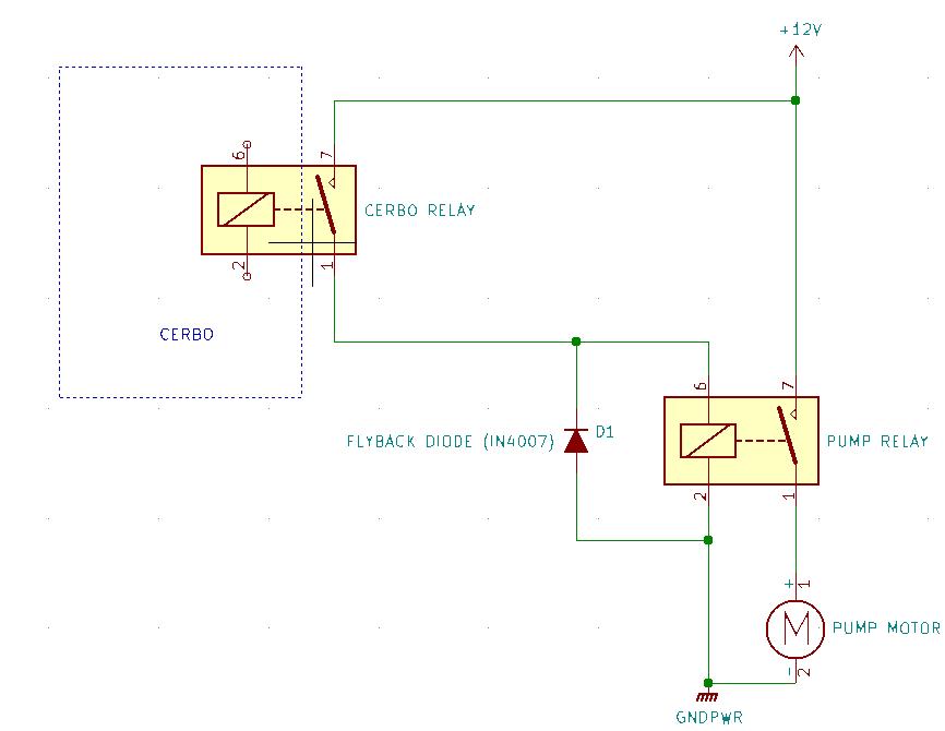
Here is where I'm stuck. I'd like to be able to control my water pump from the Cerbo. Theres a place on the display where I can turn the pump on and off. I think this is the tank pump function in the settings. All I can figure out is that I can use the Relay 1 for this but I dont know what kind of relay to buy or how to wire it properly so that it doesn't cause problems. I already have the pump wired separately to the battery bank but theres no switch so I would like to cut in the relay and send it a signal. The pump uses 7.5A 12v and its a 12v system.

Ok now Digital inputs. How do a set up a smoke alarm, CO2 alarm or a door alarm? How do I control the bilge pump? I dont understand how the digital inputs works. What sensors work for these? What should I be searching for to find sensors that work? I dont want to use NMEA or Modbus.

Thanks for any help you can provide. Hopefully we can all figure out the best ways to set these up.

cerbo gx
2 |3000

Up to 8 attachments (including images) can be used with a maximum of 190.8 MiB each and 286.6 MiB total.

3 Answers
wkirby avatar image
wkirby answered ·

The temperature sensor used for the Venus devices including the Cerbo uses LM335Z temperature sensor. It's a pretty accurate temperature device.
You can extend the lead by a reasonable amount depending upon the resistance of the wire used to extend it. I have mine extended by 10 metres and I don't notice any difference.

There are ultrasonic tank sensors with resistive outputs. BEP marine ones spring to mind:
https://www.bepmarine.com/en/ts1

Use the relay contacts of the Cerbo to switch the coil of a larger 12V relay. Wire a flyback diode across the relay coil of the larger relay to prevent back EMF from damaging the contacts of the smaller relay inside the Cerbo.


The digital inputs are just on or off signal from the contacts in devices.
It wouldn't control the bilge pump, it would be an indication as to whether it is on or off.
Is a door open or close, is a smoke alarm active or not.


8 comments
2 |3000

Up to 8 attachments (including images) can be used with a maximum of 190.8 MiB each and 286.6 MiB total.

pau1phi11ips avatar image pau1phi11ips commented ·
@Machined the onboard relay is only rated for 6A at less than 30V so an external one will be required for your pump as described above.
1 Like 1 ·
rlynch03 avatar image rlynch03 commented ·

As I understand it the digital inputs can not take 12volts. They must be limited to 3v-5v.

So a Optocoupler is needed to reduce volts in my case from 12v to 3.3-5v?

Is that correct?

0 Likes 0 ·
Fideri avatar image Fideri commented ·

@WKirby and other experts,

I realize this is a very old thread. The good thing is that power theory never changes.

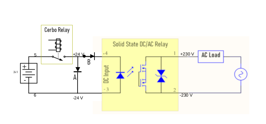
As people who understand these things more than me, I'm checking if my design to protect the Cerbo relay and therefore using an external relay makes sense? In particular:

1. Is the placement of my flyback/snubber diode "A" correct or should it be before the Cerbo across points 5 and 6?

2. Can I use an "RC snubber/absorption circuit" instead of the flyback diode at exactly the same point? There are self-contained modules comprising a resistor and a capacitor.

3. The "blocking diode" "B" might be redundant. Some circuits have it, some don't. Note that unlike the "flyback" diode, the "blocking" diode is placed inline the positive wire. The function of the "blocking" diode is said to be blocking the reverse current. This seems part of what the "flyback" diode does. But cost is not a consideration for me. If using both has no negative effects, I'm minded to install both.

Once I have clarified the above, I will provide links to the specific products I'm looking at.

1721329248992-1721329242910-1721329236783-full-cir.png

F.

0 Likes 0 ·
pwfarnell avatar image pwfarnell Fideri commented ·

Your diode A is shown the wrong way, it will always pass current, it has to be reversed so it normally does not pass current. Your LED in the solid state relay is also shown backwards.

0 Likes 0 ·
Fideri avatar image Fideri pwfarnell commented ·

@pwfarnell

Now that you mention it, that makes sense. I will make the corrections. Thanks.

F.

0 Likes 0 ·
Doug Steinfeld avatar image Doug Steinfeld pwfarnell commented ·

While it’s true that diode A is drawn backwards, there’s no need for either A or B. The purpose of a diode in the A position is to “short out” reverse current flow when the driven component is inductive such as a conventional relay coil. When voltage is removed from such a component the collapsing magnetic field introduces a reverse voltage spike that can destroy a semiconductor driver. Since your load is non-inductive (an LED) there is no reverse voltage spike when it’s deenergized. Similarly there’s no need for a blocking diode which only effect In this circuit is to drop the voltage seen by the solid state relay by whatever the Vf of the diode is.

0 Likes 0 ·
Fideri avatar image Fideri Doug Steinfeld commented ·

@Doug Steinfeld

I would tend to agree with you, except that many people on this forum disagree. There have been instances here of Cerbo contacts "welding together" and the advice has been to replace the Cerbo relays and protect them with a snubber diode whenever an external relay is used. See this link for example (among many others): https://community.victronenergy.com/questions/158046/wiring-for-relay-on-cerbo-gx.html

My set-up is exactly like in the quoted thread. As a by the way, the LED is not my ultimate load. It's part of my SSR to switch the AC which has my ultimate load. It's a resistive load which, according to many resources, further limits the usefulness of a snubber circuit.

Some resources say a snubber circuit is not needed when using a solid state relay, other resources disagree. I opted to be safe than sorry:)

F.

0 Likes 0 ·
Show more comments
Sarah avatar image
Sarah answered ·

I too share your love of the little blue box and am forever looking for new things to plug in. The Kus resistive tank sensors work well - we have installed two of them. The temperature sensors also work well both on the battery as an air temp and we have also attached them to the engine (next to the heat exchanger) to get an early warning on water flow issues. The cables have been extended by about 10 metres with a good quality cable and connectors and no problems. We have also configured one of the relays with the generator stop / start option with an external light. We did it this way because a) the generator has a nice graphical interface and b) because it has a timer built in - it’s great for leaving/arriving to the boat at night. Lastly we have the bilge pumps hooked up to the digital input so that I get notified by email if they are activated. Have considered hooking up the internal fridges so that we can remotely turn them on before arriving at the boat but decided that was too hard given that we have the doors open when the fridges are off.

2 |3000

Up to 8 attachments (including images) can be used with a maximum of 190.8 MiB each and 286.6 MiB total.

rlynch03 avatar image
rlynch03 answered ·

We have a Cerbo GX and would like to add a wind speed gauge. Does anyone know of any that are capabitalbe? The Below is listed in the Cerbo manual but I don’t know if I need their external module.

Any lessons learned would be appreciated.


https://www.imt-solar.com/fileadmin/docs/en/products/Si-RS485-Selection.pdf

1 comment
2 |3000

Up to 8 attachments (including images) can be used with a maximum of 190.8 MiB each and 286.6 MiB total.

pau1phi11ips avatar image pau1phi11ips commented ·

Says it's possible in the manual https://www.victronenergy.com/media/pg/Cerbo_GX/en/installation.html#UUID-d4b7dfe9-4ee0-53bc-8959-c567ed63cebb

0 Likes 0 ·