question

nico avatar image
nico asked

unresponsive MULTIPLUS 12-3000


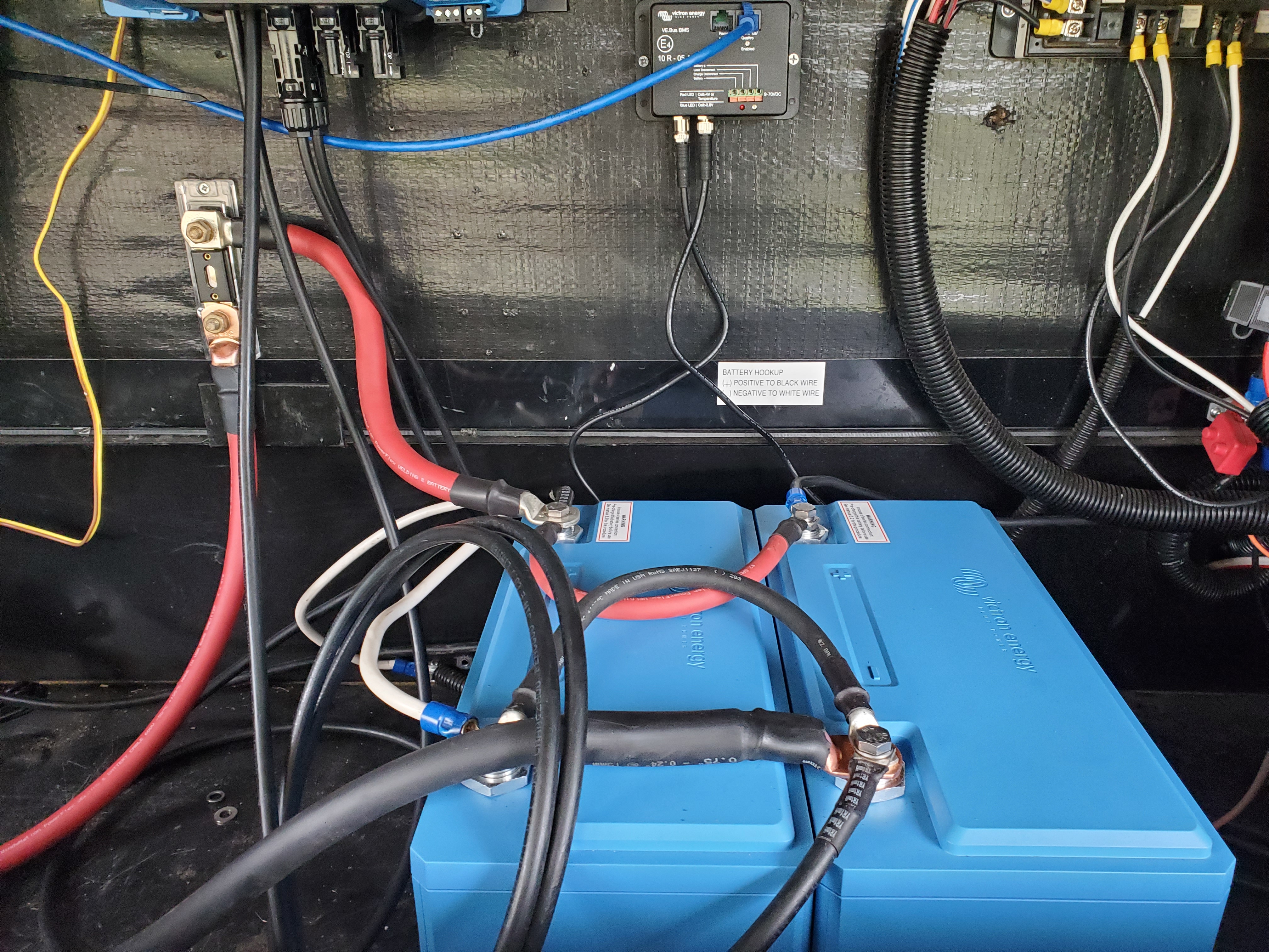
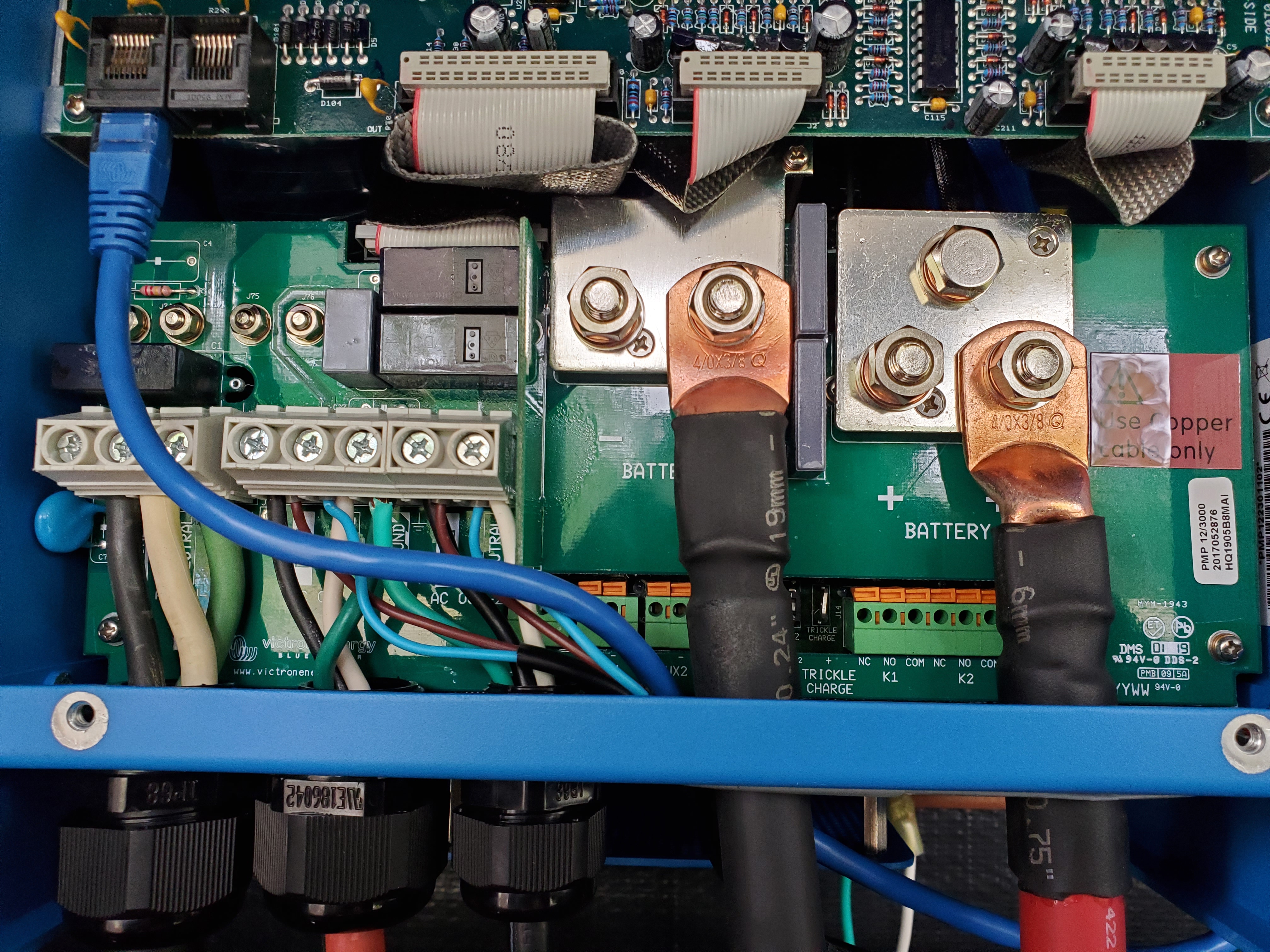
Just got my multiplus installed, completely unresponsive tho, move the [only one switch] switch up and down with no response from the machine. See anything wrong here? battery voltage is good at 13.5v, multi has voltage at its terminals and totally unresponsive..... bought from solar panel store, online dealer in Colorado.


I have ac input and 2 ac outputs wired, haven't introduced any 120, wanted to boot up the system under battery power first.....


Was really looking forward to using this to replace an AIMS inverter charger..... HELP!
Phoenix Inverter
2 |3000

Up to 8 attachments (including images) can be used with a maximum of 190.8 MiB each and 286.6 MiB total.

2 Answers
Jack Peters avatar image
Jack Peters answered ·

Has the VE.Bus BMS assistant been installed in the MultiPlus?

Have you tried turning it on with the VE.Bus connection (blue cable) to the BMS disconnected?


Edit: Also no power wires connected to the BMS.

2 comments
2 |3000

Up to 8 attachments (including images) can be used with a maximum of 190.8 MiB each and 286.6 MiB total.

nico avatar image nico commented ·

I disconnected the cat5 cable from the multiplus and the unit turned right on. So I got the inverter working, as soon as I plug in the cat5 to the multiplus from the ve bus bms mains detector it stops making power....


I have a ve bus bms and the ve bus mains detector.


Mains detector wired into the multiplus ac output 1 and 2, a cat5 from the multiplus to the mains detector, and another cat5 from mains detector to the ve bms bus.


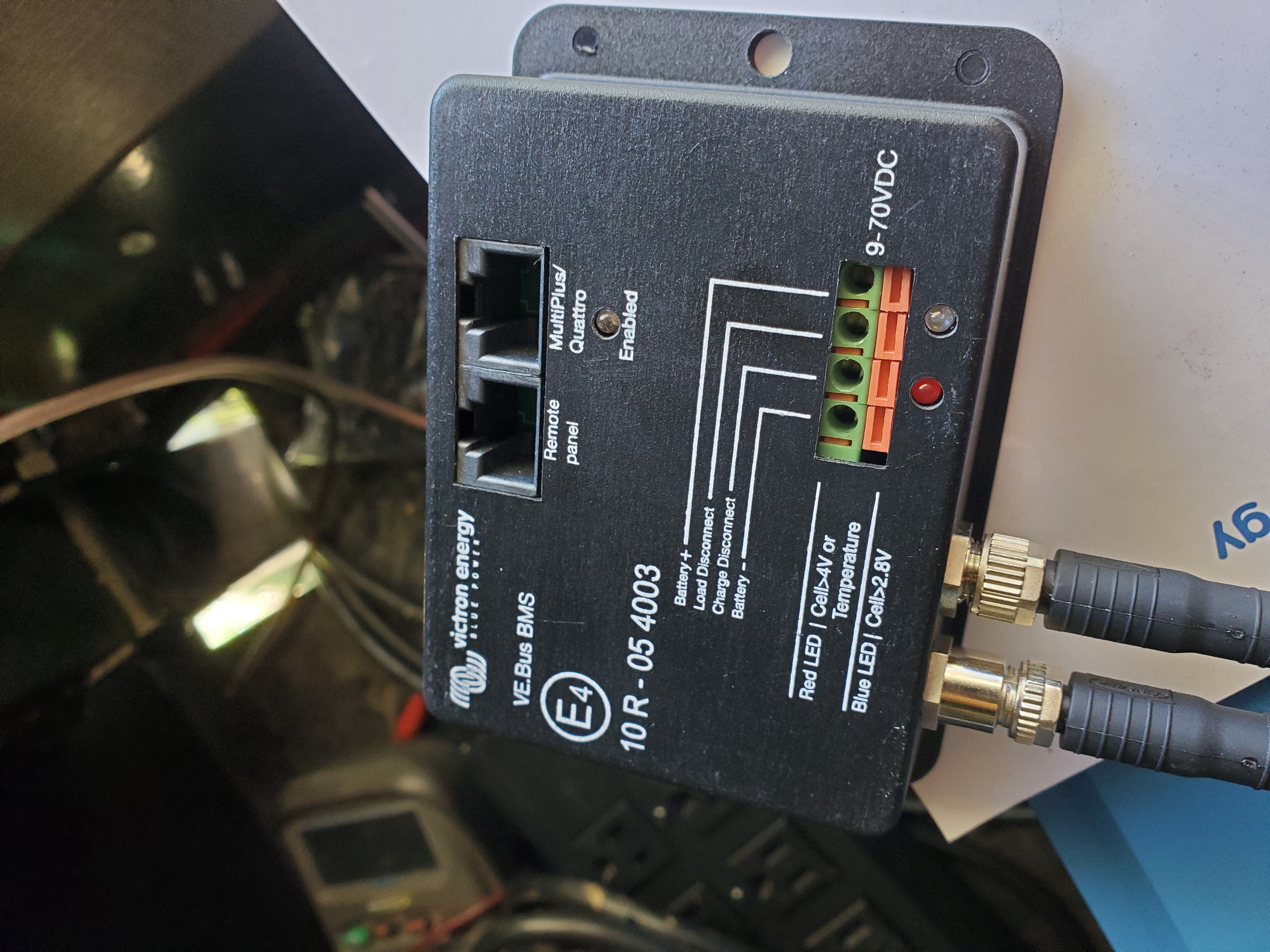
On the ve bus bms, there's 4 ports for wires, bat+/load disconnect/charge disconnect/battery-

1. Are there wires that plug into these green ports?

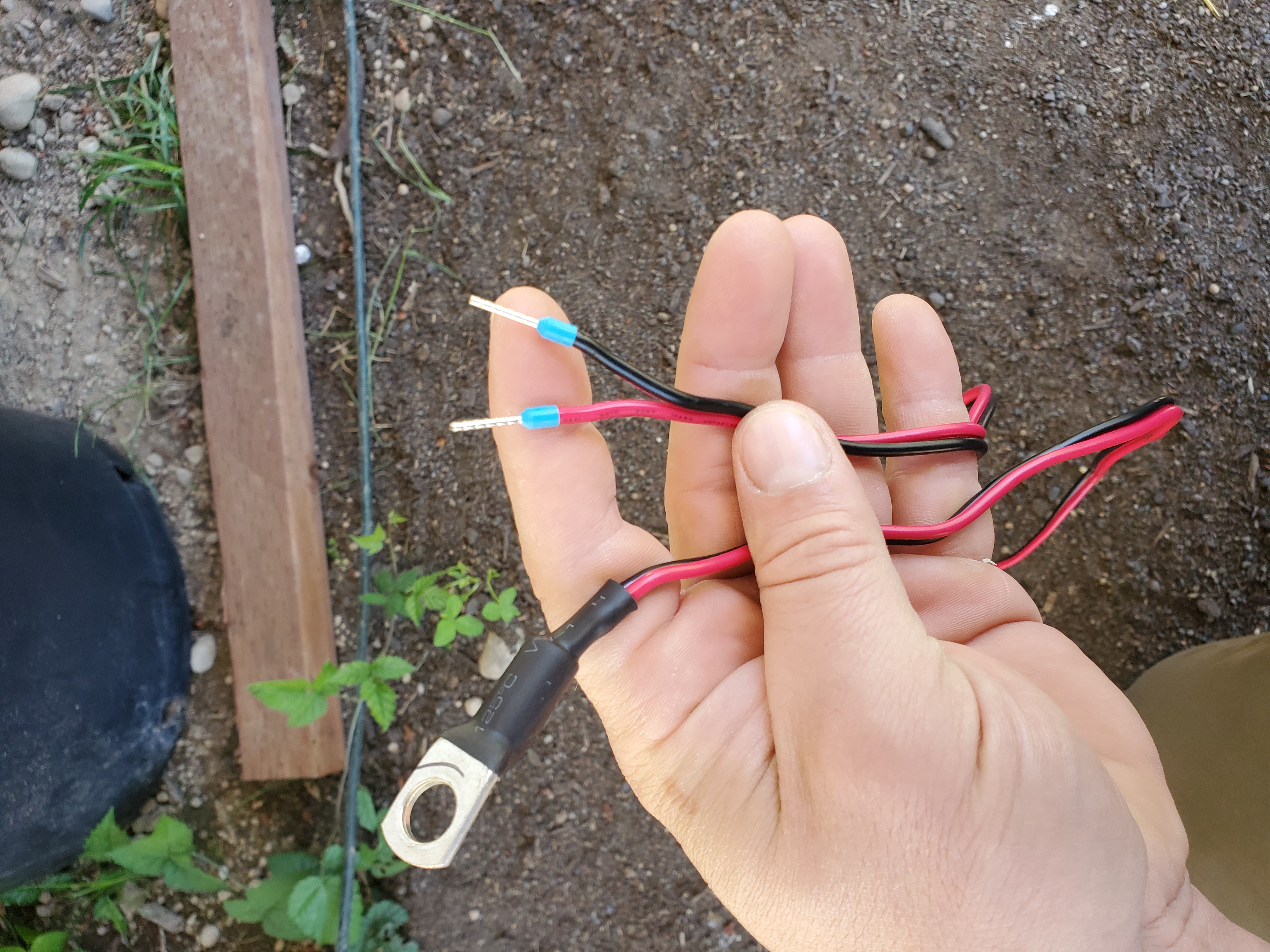
2. What is this wire for? I have a red and black set of wires that both terminate with a single battery ring terminal, and pins on other side....


I'm asking how to properly hook up wires into the green ports on the ve bus bms, wires I supply? Like just speaker wire to +/-? And how to fix wires to it.... can't see any screws to tighten down the wires....


Also, I used the victron configuration tool on my laptop to set the multiplus charger to lithium settings, that's about all I've done so far.


0 Likes 0 ·
Jack Peters avatar image Jack Peters nico commented ·

Read this: https://www.victronenergy.com.au/upload/documents/Manual-VE-BUS-BMS-EN-NL-FR-DE-SE.pdf

  • Mains detector should be connected to the inputs not the outputs.
  • You need to supply the small wires for the BMS.
  • Connect BMS + to battery + with a small wire and inline fuse.
  • The green terminal block is a spring cage type. press the orange lever, insert wire, release lever.
  • Generally wires with ferrules will work best.
  • The load disconnect and charge disconnect are described in the manual.
  • The wire in your picture is the temperature sensor of the inverter/charger.
0 Likes 0 ·
nico avatar image
nico answered ·

After disconnecting the bms from the multiplus, it turned right on. I needed to program the multiplus with the bms assistant, via mk3 to usb cable and laptop.


Supplied the bms with power, and after programming was able to have full functionality of the multiplus. I have ac output 1 for my outlets, and my ac outlet 2 which is pass through only to my air conditioning system. Transfer switch works, charger works, inverter works. All is well in the neighborhood again.


Just looking to add a ve smart bus so I can read the multiplus from the victron app.


Also looking to add a smartshunt so I can know the state of charge on the batteries vs guessing on voltage, which is impossible with lithium....

2 |3000

Up to 8 attachments (including images) can be used with a maximum of 190.8 MiB each and 286.6 MiB total.