question

marks avatar image
marks asked

Batteries in Parllel

Dear community,


I have a question concerning connecting batteries in parallel. Specifically I have 2 Victron Energy 165Ah Gel batteries and want to connect them in parallel to have an overall capacity of 330 Ah. I have several questions

a) Is this possible without any precautions, can I just connect the batteries in parallel, + to + and - to -? Since the inner resistance of the batteries is basically 0, won't there be an enormous current when I connect them or does this just work? Or do i need some sort of current limitation or so?

b) What kind of cables would you recommend? I assume they should have the same thickness as the cables provided with my Multiplus Compact 800VA?

c) Where should the temperature sensor be connected?

d) If I had a second Multiplus Compact 800 VA, can one be connect to one battery, the other one to the other battery and then the batteries connected (assuming e.g. differen sources of power, i.e., wind power on one inverter and solar at the other inverter)? Or does this make no sense?

battery
2 |3000

Up to 8 attachments (including images) can be used with a maximum of 190.8 MiB each and 286.6 MiB total.

5 Answers
Kevin Windrem avatar image
Kevin Windrem answered ·

To minimize current when two batteries are connected in parallel, you should charge each one to 100% independently. Then, check the voltages of both batteries. They should be very close to the same. If not, there is probably an issue with one of them.

There will be minimal current when making the parallel connection if the batteries are at the same voltage. The key to balanced loading and charging is to use the same age and type of battery in any array.

Cable size is a function of load. You should find recommended cable sizes in the manual for Victron inverters. Use the same size cable between the batteries.

For best balance, connect the load positive to one battery and the load negative to the other. Or use bus bars with the same length cable to both negative terminals and the same length cable to both positive terminals. Keep all connections as short as possible.

Temperature sensor can go to either battery. It doesn't matter.

Treat the two batteries as one. Connect all loads and charging sources including multiple inverters from the same battery connections. Use bus bars if you have a lot of connections. That also makes it easier to remove a battery for testing/replacement.


2 |3000

Up to 8 attachments (including images) can be used with a maximum of 190.8 MiB each and 286.6 MiB total.

dazey77 avatar image
dazey77 answered ·

a) No. You need to make sure both batteries are fully charged so that when you connect them, there is no big charge movement between the two. For wiring diagrams and take off points check the victron wiring unlimited free ebook (google it)

b) as thick as possible really and as short as possible (while keeping lengths equal) but those cables would be a sensible starting point if thats your only load.

c)on the battery that could get the hottest

d)No, you can't draw down from individual batteries if they are wired in parallel. You would have to choose between connecting both multiplus to the pair or splitting the battery pair and having a multi on each. If the multis are paired together (parralel operation) then they have to use a single battery bank.

2 |3000

Up to 8 attachments (including images) can be used with a maximum of 190.8 MiB each and 286.6 MiB total.

marks avatar image
marks answered ·

Thanks for the quick replies and for the tip with the victron energy wiring book! Also the bus bars seem to be a good a good approach!

2 |3000

Up to 8 attachments (including images) can be used with a maximum of 190.8 MiB each and 286.6 MiB total.

outsourcedguru avatar image
outsourcedguru answered ·


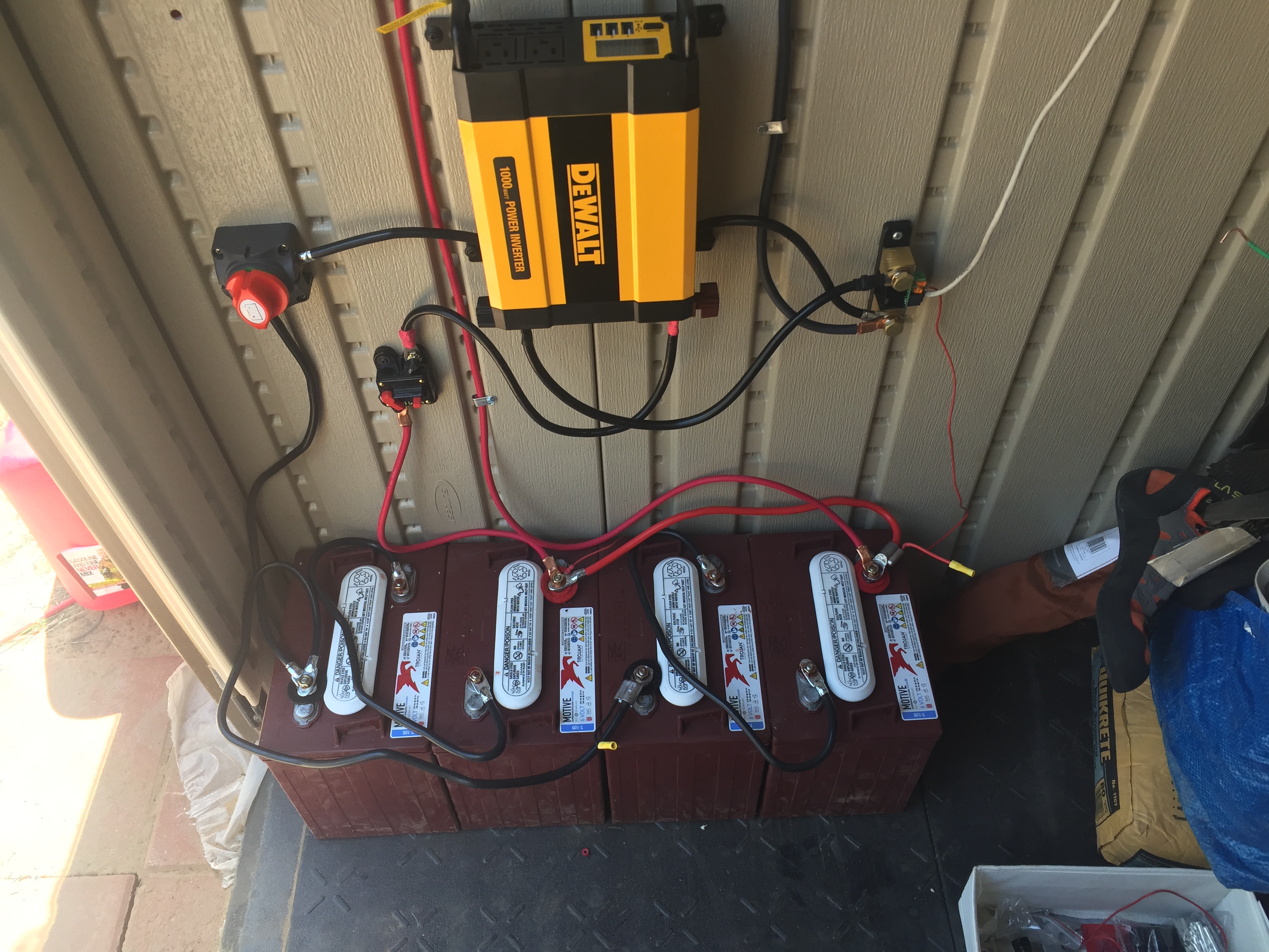
Here's a picture of my setup, noting that you can zoom in for good detail. Also note that I've moved the black lead from the MPPT (above and outside of photo) to the top of the shunt on the right instead of the bottom). I have 6V batteries here. I'm therefore doing series + parallel to present 12V to the charge controller and to the inverter.

Most of the cables are directly from O'Reilly Auto Parts. They're the 24" battery starter cables and they're rated 4 gauge and fit beautifully over the screw connections on my batteries. To make it more idiot-proof, I dropped two pairs of those red/black felts on top to highlight the polarity from a distance. I changed things up on two of the jumpers, using O'Reilly's version which includes a small jack; I could then tap off 12V from one of those yellow connections to the other if I wanted to manually test with a voltmeter, setup some other kind of testing device or get power outside of the safety switches.

To the best of my knowledge, all wire above this level is also 4 gauge except for the tiny red test wire for the Victron Voltage Monitor.


img-0303.jpg (2.2 MiB)
1 comment
2 |3000

Up to 8 attachments (including images) can be used with a maximum of 190.8 MiB each and 286.6 MiB total.

dazey77 avatar image dazey77 commented ·

Makes sense to have moved the MPPT.

Some specific issues in the wiring as it stands

The second battery pair have a longer ground route than the first. Not sure if you can get two cables in your isolator and fit a longer cable to the first pair to match the second pair?

You are drawing load biased to the first pair and charging biased to the second pair due to cable length differences (assume the vertical cable is the MPPT incoming. I would again try and wire both pairs to the circuit breaker with matching lengths. You could take the MPPT to the CB.

0 Likes 0 ·
lklmenterprises avatar image
lklmenterprises answered ·

Mostly everything already answered what you should require.

Something extra, Ideally for Batteries of larger current capacity you should include fuses appropriate to them.

Make sure you are using Bus Bars to distribute your DC source.

So as example for 100a Batteries - on the Positive side.

Batt 1 > 150a Fuse > Bus Bar

Batt 2 > 150a Fuse > Bus Bar

then

Bus Bar > Battery Isolating Switch > 200a Fuse > Inverter

Bus Bar > Battery Isolating Switch > 50a Fuse > Battery Saver (disconnect at programmed low voltage) > DC Circuits (lights, devices, etc.)


In all of this if you want to measure DC Power usage, include a Shunt in the Negative line.


With Question d;

Whilst it will work, the fact it is in Parallel means any power usage for one side of the circuit will draw from the other side of the circuit, causing a potential for over current through the lines from one circuit to the other, this goes against the theory behind why you use Bus Bars and Battery cables of Same length.

Whatever you do, do not further consider having the 2 x 12v in Series and then connecting one Inverter to one battery and one to the other, this will invariably cause imbalance.

2 |3000

Up to 8 attachments (including images) can be used with a maximum of 190.8 MiB each and 286.6 MiB total.

Related Resources

Additional resources still need to be added for this topic