question

rockatron avatar image
rockatron asked

Tesla Model S battery + Multiplus = Can not turn on inverter below 50% SOC.

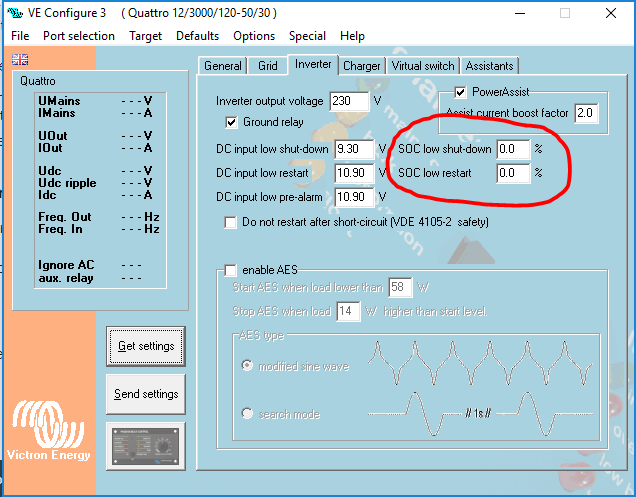
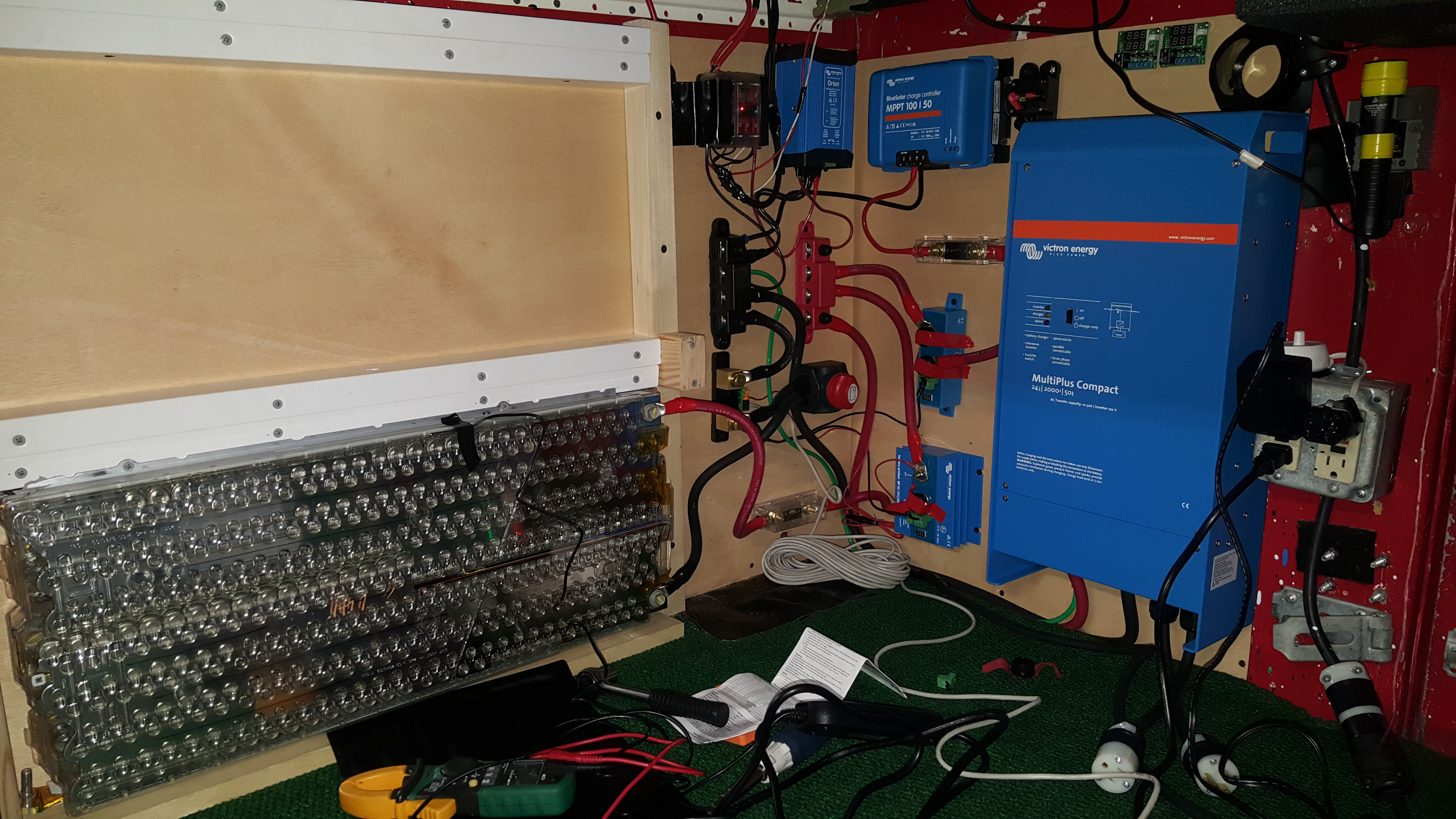
Anyone else using a Tesla battery? I'm surprised to find that I can not turn on my inverter below 21.8V. Do I have to return this inverter?

The tesla battery is supposed to be 20% SOC at 19V, 100% SOC at 25V. Please help me utilize my full battery. Thanks.

MultiPlus Quattro Inverter ChargerLithium Battery
2 |3000

Up to 8 attachments (including images) can be used with a maximum of 190.8 MiB each and 286.6 MiB total.

17 Answers
mvader (Victron Energy) avatar image
mvader (Victron Energy) answered ·

Hi all,

Good news! Last week we released a new version of VEConfigure. The minimum DC Low Restart has been lowered for 24V models from 21.8 to 20.6, and from 43.6 to 41.2 for 48V models. Unfortunately, we have not been able to reduce this minimum for 12V units, due to hardware limitations.


More information in this blogpost:

https://www.victronenergy.com/blog/2019/07/17/ve-bus-firmware-460-veconfigure-and-venus-os-v2-33/

UPDATE 2019-09-10: we'll also decrease the hysteresis soon. See here: https://community.victronenergy.com/questions/1366/feature-request-allow-dc-input-low-restart-voltage.html?childToView=28892#answer-28892

52 comments
2 |3000

Up to 8 attachments (including images) can be used with a maximum of 190.8 MiB each and 286.6 MiB total.

Jay Kote avatar image Jay Kote commented ·

This is excellent news! I can let one of my customers who installed another inverter know. They held off on doing their solar until all this was worked out as they wanted victron system with the Color GX.

(We will do a buy back of the inverter we installed for them when they install the victron system with us.)

Thank you

0 Likes 0 ·
Tom avatar image Tom commented ·

Thank you for the software update. Do we need to do any firmware update to the Multiplus 24/3000?

Tom

0 Likes 0 ·

It’s not necessary to update the firmware of the inverter/charger to use this change.

0 Likes 0 ·
Meine_Energiewende avatar image Meine_Energiewende Daniël Boekel (Victron Energy Staff) ♦♦ commented ·

Hi Daniel,

just installed FW 461 and newest Ve.Configure. At first i could not change the values. Then i used the "restore Defaults" button ..... then the new values were available.

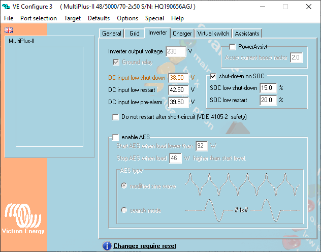
But why must the restart value stay 4 volts above shutdown voltage ? If i change the shutdown voltage to 38.2 Volts, restart voltage can only be set to 42 volts.

Please have a look at the screenshots:

Thx

Jens

0 Likes 0 ·
victron1.png (38.5 KiB)
victron2.png (39.8 KiB)
Daniël Boekel (Victron Energy Staff) avatar image Daniël Boekel (Victron Energy Staff) ♦♦ Meine_Energiewende commented ·

Hi @stxShadow
Changing the 4 volt delta is on the wish-list, no indication if / when but it will be looked at.

0 Likes 0 ·
Daniël Boekel (Victron Energy Staff) avatar image Daniël Boekel (Victron Energy Staff) ♦♦ Daniël Boekel (Victron Energy Staff) ♦♦ commented ·

In the latest ve.configure connect the delta is reduced to 0,5V for 24V systems, and 1V for 48V systems.

0 Likes 0 ·
Tom avatar image Tom Daniël Boekel (Victron Energy Staff) ♦♦ commented ·

Great news

0 Likes 0 ·
steveca avatar image steveca commented ·

MVader,

Thank you and your staff for the much needed updates that will now facilitate the use of Tesla 6s and 12s (in series) modules. This is a huge win for the secondlife storage market. To my knowledge, Victron has the only inverter charger with ATS that works with Tesla Modules. There is another company that custom designed an inverter to work with Tesla modules, but it lacked the charger and ATS component as well as app based configuration abilities.

Thank you for listening!


Steve

0 Likes 0 ·
Tom avatar image Tom commented ·

I down loaded the updated VEconfigure3 software V 90.04.213 to adjust my Multiplus 24/3000 50-70 (110 volt AC)but the lowest it allows me to set the DC input low restart is 21 volts and not the 20.6 volts in the thread that Mvader posted. Is there something I am missing or not setting correctly?
I can see when using a fake target it does show the option for min value 20.60 V?

What am I doing wrong?

0 Likes 0 ·

Hi @Geriakt

What voltage did you set the shutdown value?

0 Likes 0 ·
Tom avatar image Tom Daniël Boekel (Victron Energy Staff) ♦♦ commented ·

The shut down is set at 19 volts

0 Likes 0 ·
Jay Kote avatar image Jay Kote Tom commented ·

Hi,

Were you able to get a resolution? If so, hope you will share the outcome.

Waiting on this for customer. Want to make sure if we get 24V Unit it will work now. Otherwise risk paying ship and restock fee out-of-pocket.

Thanks,

0 Likes 0 ·
steveca avatar image steveca Jay Kote commented ·

I read elsewhere on this thread that the LVC must be set 4 volts lower than the inverter restart LVC in order to lower the restart LVC to 20.6V. That would make the per cell low voltage cutoff 2.766 per cell. Presumably that is okay if you use a separate battery protection device with a higher cutoff set at say 3.0V per cell or 18.0 volts.

0 Likes 0 ·
steveca avatar image steveca Jay Kote commented ·

Here is the discussion. It seems that there may still be some bugs to fix before we get what we want: https://community.victronenergy.com/questions/1366/feature-request-allow-dc-input-low-restart-voltage.html?childToView=25736#comment-25736

0 Likes 0 ·
Jay Kote avatar image Jay Kote steveca commented ·

Thanks for sharing. I think it's best to wait for the dust to settle on this.

0 Likes 0 ·
Tom avatar image Tom Jay Kote commented ·

have my DC Voltage shut down set at 19 volts for my Tesla 6S 444 modules. I see playing around with he software if the DC Voltage Shut down is set at 18.6 volts then you can set the Start up at 20.6 volts, so I think it needs a 2 volt delta. I also have a Victron BP 220Amp set at t a 19 volts shut off.

0 Likes 0 ·

Hi @Geriakt,

A Battery Protect should NOT be installed in a situation where current could flow both ways (like an inverter/charger). There is a bit more info here.

0 Likes 0 ·
Tom avatar image Tom Guy Stewart (Victron Community Manager) ♦♦ commented ·

I find this troubling to hear when there is no documentation about this with and BP220. Plus the fact you sell a Victron branded BP and Multiplus and Quatro inverter chargers. Now I guess I spent $300 on my BP220 and BP60 for nothing. Also I had a Victron Dealer say the way I am using my BPs are the correct way to use them.

I use the BP60 coming off my solar MPPT connected to a battery monitor over voltage relay the connected back to the BP220 input as a back up over charge protection.

Do you sell a BP device that will work with an Inverter/charger? If I remove the BP220 do you recommend I install a device like a Tyco/Kilovac Contactor/Relay connected to a device like the Victron 712 to relay out a programmed over and under voltage?

I assume you are recommending I remove the BP220 from the Inverter and just use it between my 24 volt battery appliances.

Is there a way to return my BP220 and BP60 back to Victron or trade for a different device to recoup my loss?

Tom

0 Likes 0 ·
Tom avatar image Tom Tom commented ·

Guy,

Based on your comments and extend thread, I will remove my BP220 that is placed between my Multiplus and battery and replace it with a Tyco IHV200HAANA contactor relay connected to a battery monitor with a programable low voltage and over voltage relay to provide some added safety protection. I will also remove my BP65 that is between my MPPT charger and battery as the Contactor relay can provide both functions.

I do want to ask if I can just move my BP220 outside of the charge loop and place it between my 24 volt system and Multiplus or is it not advised to have a Victron BP connected to any part of the system that includes a Multiplus?

Tom

0 Likes 0 ·
Tom avatar image Tom Guy Stewart (Victron Community Manager) ♦♦ commented ·

Even in the photo attached to this thread it shows a BP220 with the Multiplus charging through the BP220.

I see a schematic using the BP100 out of the charging line and just protecting the 12 VDC out.

0 Likes 0 ·
rockatron avatar image rockatron Tom commented ·

Hello Geriakt,

I am original poster in regards to the Tesla Modules and I just wanted to give thanks to you and all the other users who helped maintain pressure on Victron to resolve the original issue of the 21.8v limitation for turning on this inverter. A friendly reminder to everyone that this took Victron 8 months to remedy this issue and there were even points when we were told that it was never going to be fixed.


At the time of my original post Jan 14, 2019 - my only valid complaint is that this 21.8v stipulation was not mentioned in the manual, as the manual clearly stated that the "DC input low restart" is only supposed to be in effect after the inverter reaches the much lower "DC input shut off" value. I also appreciate other members pointing out that the manual clearly stated 19v-33v input usability for the inverter.


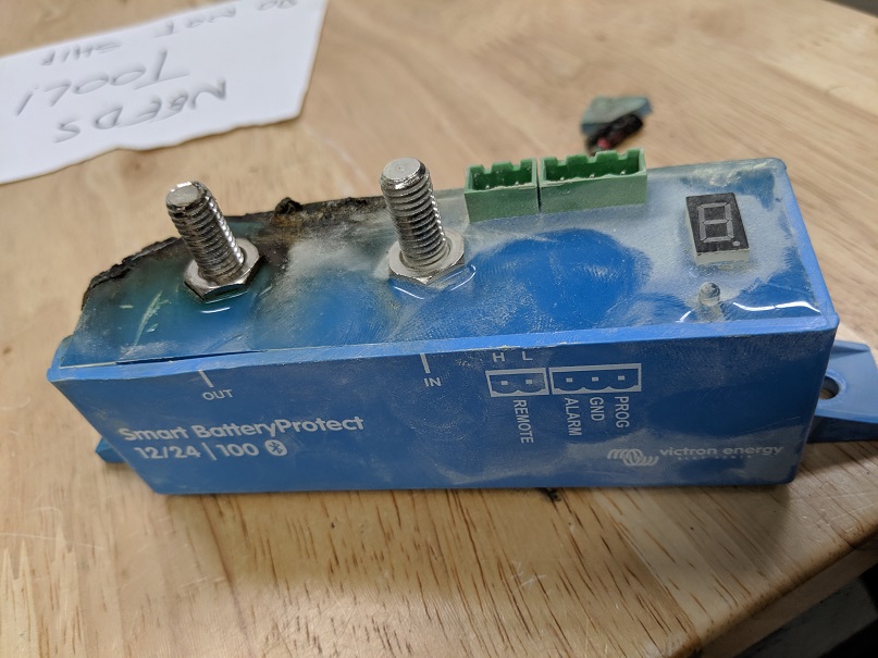
So now I am writing this new post to share my thanks in your bringing this new Battery Protect issue to my attention. The following thread was brought to our attention by Victron Staff Guy Stewart (https://community.victronenergy.com/questions/2030/vebus-bms-with-2-battery-protect-alternative-layou.html) and it seems EXTREMELY important. I was very surprised to see a picture of a BP100 that clearly caught fire, so I will repost it here to make sure everyone sees it.


Honestly, I had seen so many examples on websites & YouTube where people were using a Victron BP module allowing current flowing in both directions, it had never crossed my mind that this would be considered dangerous by Victron.


EDIT ** I now see the caution listed by Victron at the very end of the manual beyond the setup diagram, not in the actual "Engligh" or any other foreign language instructions. Also the website now clearly states this issue on the listing page, which I do not remember seeing when I purchased mine 8 months ago. **


Now that my rant is over, I really do not have much helpful information to provide to this new issue. As the picture in my original post shows, I have been using the BP220 with current flowing in both directions with no issues for over 8 months now. I believe the BP220 is metal as opposed to the BP100 plastic which I'm sure helps dissipate the heat, but mainly my max amp load is a 20amp drain / 30amp charge from my Multiplus24/2000/50....so nowhere near the 60AMP charging load that caused the BP100 to fail as pictured above.


I dunno.... I'll probably remove the BP220 from the charing path and place it between my 12v distro and the battery which is where the over discharge is most likely to happen. I'll let the inverter do it's thing and hope its' low voltage shutoff doesn't fail. Either way, thanks for bringing this to my attention and I share in your frustration.

0 Likes 0 ·
Tom avatar image Tom rockatron commented ·

As much as I am upset to learn of the charge flow issues with the BP220, 100, and 65. I am happier to be informed by Guy of the possibility of a melt down or fire hazards. Now there was no need for me to spend the extra money on the BP220 as the BP100 would be sufficient. I am moving my BP220 out of the charge path and just placing it in a one way path for my 24 VDC output buss bar. I will have to have faith the Multiplus will shut down at 18.6 volts LVSO. I also plan to install a Tyco IHV200HAANA Kilovac Contactor programed with a battery monitor for LVSO and HVSO. Brand new $40.

The Victron VW Van Electronics Install Schematic is very helpful to show proper placement of Victron BP.

I would like to know if you have used the Generator Start/Stop relay on the Multiplus? How did you set it up and program the assistant?

Tom

0 Likes 0 ·
mvader (Victron Energy) avatar image mvader (Victron Energy) ♦♦ Tom commented ·

Hi @Geriakt (and all the others), Geriakt, you wrote:

> I will have to have faith the Multiplus will
> shut down at 18.6 volts LVSO. I also plan
> to install a Tyco IHV200HAANA Kilovac
> Contactor programed with a battery
> monitor for LVSO and HVSO. Brand new
> $40.

Please be ware that that won't be enough. Perhaps you already have proper safety measures in place, but maybe you don't, so I'm writing this down for you and also for benefit of other people coming accross this post (we'll later explain this more widely too; rather than just hidden deeply in here as a comment):

Here it goes:

To make for a safe lithium system; there must be a mechanism in place that automatically disconnects the battery from the rest of the system on cell under-voltage, over voltage and also on cell-temperature issues. This means that for each cell, its voltage needs to be measured. And also temperature needs to be measured and monitored; preferably at cell level, but usually also OK to measure it for a certain number of cells together.

These features are usually taken care of by a BMS. At Victron we do make BMS-es, but they are only to be used with our own batteries. We do not make general purpose BMS-es.

To make for a safe system, you'll need to get a BMS that measures at cell voltage level. Having a Tyco that operates at total pack voltage is not safe. And since our equipment also looks at total pack voltage (only), it will also not be safe.

Please take this seriously, any Tesla or other cell over and under voltage can lead to explosive fires and other severe issues.

For which at Victron we take zero responsibility and also accept no liability at all. Its the responsibility of a BMS to disconnect the battery in case of issues; not of the Victron equipment.

I'd like to help by recommending BMS-es; and I know that at least one company you can consider is REC-BMS: https://www.rec-bms.com/. And I'm sure others active here will have more recommendations.

Lastly, note that there is a distinction between the aggressive chemistries (like in the Tesla cells) and the "safer" LFP chemistry. Definitively for the aggressive ones you need safety measures. The safety risks are less with LFP; but you'd still want one for longevity reasons, and also we do require one / take no responsibility for any safety issues with those either.

(end)

----


Then on the 2V delta (which is for 24V, its 4V for 48V) open issue: be informed that its on the list to be checked if we can make that lower by someone now on summer holiday; will take a little while longer.

And lastly, you wrote somewhere that initially all you asked for/complained about was the documentation not being correct; and that it took a long long time for anything to happen. I can't find that text now, but you're absolutely right and we haven't handled that well. We should have started by fixing the documentation. My apologies; I'll make sure its changed to be clear;

3 Likes 3 ·
Tom avatar image Tom mvader (Victron Energy) ♦♦ commented ·

I want to thank you for replying to my posts. I know you are the owner and I feel you care about Victron customers. You don't see that much in business these days so again thank you.

Yes I take the safety of using the Tesla Battery a serious issue and I am taking steps to make my system as safe as possible when I can not monitor it directly. I also know this chemistry is not as safe as LiFePo4 as well as Lead Acid can also explode. I thought by using the PP220 I was adding an additional level of safety, but I was ignorant on fully understanding how the BP220 works so I am removing it from the charge path and using it only at the 24VDC buss in the proper electrical path. Yes I am aware of the Rec BMS system and understand it can also communicate with Victron equipment so yes I am researching the Rec BMS and how it works with a powered contactor. I do monitor my individual cells in the 6s Tesla modules to watch out for out of balance. I will read up on how the Rec BMS can shut off the contactor if one cell should get out of balance. I only charge my Tesla to 24.4 volts or 4.07 volts per cell so I would have to be well out of balance to over charge. I am also looking into other aftermarket BMS systems available to me.

The Victron VW Van posts have been very helpful in understanding where the BPs can and should be used.

The power on at low voltage set at 20.6 volts or 21 volts is workable at this time for me as I do have a generator that can get me over the threshold. Your comments Victron is still looking at or working at to improve this is also encouraging for me and others that use this 6s system. Sure if we were able to use a 7s configuration this would not be an issue, but it just is not possible unless you construct a complete battery system with the Panisonic 18650 cells.

Again thank you for taking the time to respond and point out safety issues.

I will look for the new thread to continue to contribute.

Tom

0 Likes 0 ·
Jay Kote avatar image Jay Kote Tom commented ·

The BVM had a thermal sensor. Couldn't this be tied to some cut-off on thermal problem.

And like wise voltage protection.


The Tesla batteries are designe to handle 300 - 500 amps from what I understand. Most customers will not draw more than 200 amps. (Maybe an ocassional 230-250). With only a fractional draw to the C rating, and using BVM, and have inverter cut off at 20.1v -- not rate 19v. I think you are safe without a BMS at the cell level.

Also keep max voltage to say 23.5 and not 24v. (Tesla go all the way to 24.6v, if you push hard.)


So now you have safe low and high voltage.


I suppose one other precaution might be an alarm to detect some weird condition. Most RV stick a pretty good smell sensor. They are so sensetive that they will go off with alcohol sprayed 2 ft away. Maybe vent the Tesla battery compartment to this. Then if there is some odor due to melt down you would get alarm so you can evacuate.


Those are a lot of safe guards. And there are some who say a BMS is not necessary at all.

It's a tough call.

0 Likes 0 ·
Tom avatar image Tom Jay Kote commented ·

My Tesla 444 74p6s can have a max charge to 25.2 volts. Now I do not want to charge that high so I have set my charge at 19-24.6 volts. I think that will provide about 4kwatt hours.

I do employ a manual battery balancer, but have never had to use it.

I am currently testing the thermocouple in the Tesla battery connected to both my battery monitor and a thermostat to control relays for under and over temperature cut off. I also to liquid heat my Tesla under 40 deg C so I don't damage it when charging at low temps. There is no need to cool the battery with the low loads I am pulling.

I did notice when I first used my Victron BP s they did give off a funky smell of burning sweet rubber.

0 Likes 0 ·
Jay Kote avatar image Jay Kote Tom commented ·

Hey thanks for sharing. It's really nice to get the scoop on Tesla from real users.


I haven't done it, yet. But we have a customer who has one. I'm waiting for dust to settle on LVC before I call them and promise what we can't deliver.


We have them on another inverter loan for now they seem satisfied. But they want all Victron because they want touch monitor.


The wife says she wants it cause she actually can operate it.

0 Likes 0 ·
Show more comments
ben avatar image ben ♦ Tom commented ·

Tom,

You may be able to use the BP to detect the LV cutoff and trigger your remote relay, if you like, rather than trusting the inverter to shut down itself.

But, if you have an expensive battery, you may wish to implement a BMS to handle the management completely.

Separately, it would be best to pose your other question as a new Question here. This site makes it very difficult to read once commentary gets deeply-nested.

0 Likes 0 ·
Tom avatar image Tom ben ♦ commented ·

Thank you for your comments and suggestions. I will be removing my BP220 and using a Tyco Contactor that can work with a remote trigger relay that can be used in both directions.

I am looking to improve my BMS system to work directly with the Tyco contactor for LVSO and OVSO in the complete system and individual cells.

The BP will be moved to be used just at the 24 VDC buss bar as it has been designed.

0 Likes 0 ·

Hi @Geriakt

If you use a contacter between the battery and a capacitive load, like an inverter, don't forget to include a pre-charge device.

If you don't you will damage your contacter very quickly.

0 Likes 0 ·
Tom avatar image Tom Daniël Boekel (Victron Energy Staff) ♦♦ commented ·

I was considering a pre-charge device, but I can't find one in the states. Can you offer up a recommendation?

I was looking for the Rec Pre-charge 11-68 VDC but the are no options in the states for it.

Tom

0 Likes 0 ·
Rob Duthie avatar image Rob Duthie Tom commented ·

You make your own precharge device, it is very easy only a resistor and a contactor required.

0 Likes 0 ·
Show more comments
steveca avatar image steveca Tom commented ·

That is good news. Elsewhere folks have reported a 4 volt delta. A 2 volt delta is perfect for my needs. I have no issues using a LVC set at 18.6 volts in order to get the restart voltage to 20.6V. That is still 3.1 volt per cell which is fine, especially under load.

0 Likes 0 ·
Tom avatar image Tom steveca commented ·

I think the 4 volt Delta is on the 48 volt inverters.

0 Likes 0 ·
steveca avatar image steveca Tom commented ·

That makes sense. Glad it is a 2 volt delta which is perfect

0 Likes 0 ·
Jay Kote avatar image Jay Kote Tom commented ·

Have you seen the post that says BP is not meant to be bi-directional? (Assuming I understood correctly, because seems odd.)

0 Likes 0 ·
rockatron avatar image
rockatron answered ·

FYI this limitation is imposed by the "DC input low restart" value which has a minimum value of 21.8V.

2 |3000

Up to 8 attachments (including images) can be used with a maximum of 190.8 MiB each and 286.6 MiB total.

rockatron avatar image
rockatron answered ·

My research shows Tesla Model S battery:

18V = 0% SOC

21.6=50% SOC

25.2=100% SOC

2 |3000

Up to 8 attachments (including images) can be used with a maximum of 190.8 MiB each and 286.6 MiB total.

Rob Duthie avatar image
Rob Duthie answered ·

Add more packs in series to get the right voltage!

5 comments
2 |3000

Up to 8 attachments (including images) can be used with a maximum of 190.8 MiB each and 286.6 MiB total.

rockatron avatar image rockatron commented ·

I appreciate the idea but to be clear, there is nothing wrong with the voltage. There is simply a parameter in VEconfig which cannot be properly modified and what confuses me is that this parameter doesn't even protect the battery from being over discharged, it simply prevents you from turning the inverter back on when below the "DC input low restart" threshold.

0 Likes 0 ·
Jay Kote avatar image Jay Kote rockatron commented ·

Did you try to talk to VIctron Engineer. I don't know if you saw this, but a reseller told me to change it means changing an external dip switch and the software setting. I'm wondering if you need to get info on the dip switch?

0 Likes 0 ·
oxy avatar image oxy commented ·

Adding one more Tesla pack in series would transform the system to 48V (though also a "low" voltage one).

0 Likes 0 ·
Jay Kote avatar image Jay Kote commented ·

Not in my customers budget ... lol.

0 Likes 0 ·
tell-me-more avatar image tell-me-more commented ·

tesla module is 6s so adding another would take you to 12s which is not going to work...

0 Likes 0 ·
brock avatar image
brock answered ·

I think this is a glitch in the software. I am having this problem also. If you start your inverter above 21.8V and leave it on then you can draw the battery down to your low voltage cut out. It's only when you try to turn on the inverter below 21.8V then the restart voltage set point seems to be not allowing it to start. Too me the only way the restart voltage should come into play is after it has hit the low voltage cut out voltage. (This is not the case). The bp-220 will close even under the restart voltage. But if the alarm voltage is hit then the battery voltage must go above a set point before it will restart. I believe this is to prevent short cycling. I am no expert!!! I could be way off but every restart setting I have ever seen only takes affect after shut down value has been triggered. How fully we just have something set wrong and a Victron tech will chime in. I really like the inverter and hope I don't have to return it.

1 comment
2 |3000

Up to 8 attachments (including images) can be used with a maximum of 190.8 MiB each and 286.6 MiB total.

rockatron avatar image rockatron commented ·

THANK YOU!!!!!!

0 Likes 0 ·
wkirby avatar image
wkirby answered ·

That is a nice install.

You are running too low of a Voltage for a 24V system. 25.2V is below float Voltage for lead batteries or even LiFePO4, yet it is 100% for the setup that you are using.. Like Rob said, you need to run 7S with that battery chemistry. It like a lead-acid guy trying to run 11S or a LiFePO4 guy trying to run 7S, there are not enough series cells. An extra 3.7V will solve all of you problems.

The Multiplus works on quite a wide input Voltage range, but there have to be limits. Too low of a Voltage causes higher current, and a line must be drawn somewhere. It can go right up to 33V. You can see that there is more headroom above the 24V nominal, than below. With those parameters you can then design you own custom battery pack, no problem. The Tesla battery pack will work well if you use the right number of series cells.

If you check out the DIY power wall project's that people are doing all over the place, they all run 7S for 24V systems so that they are within the design parameters of their inverters.

Another advantage is that the MPPT controllers will be happier with a higher system Voltage.

1 comment
2 |3000

Up to 8 attachments (including images) can be used with a maximum of 190.8 MiB each and 286.6 MiB total.

tell-me-more avatar image tell-me-more commented ·

Unfortunately there's no easy way of running 7s with the tesla module. Unless there's something I am missing? Each pack is 6s so you could do 12s easily but that gonna be way too high.

0 Likes 0 ·
boekel avatar image
boekel answered ·

I've been using 6s batteries for a while now, Tesla modules (6s) are pretty much empty below 20 volts (3,3v per cell) so yes you can't start the inverter on an empty battery, but you really only miss the bottom 25-30%. If that's a problem I'd add more capacity.

Also, when pluggin into AC (shorepower) the system wil also start.

Further: if you want Li-Ion batteries to last, don't charge them above 4,1V too often. and:

BMS! use a bms, there are some solutions to use the tesla bms boards ( SimpBMS by Tom de Bree).

If you charge these modules with standard lead-acid voltages, they WILL catch fire.

15 comments
2 |3000

Up to 8 attachments (including images) can be used with a maximum of 190.8 MiB each and 286.6 MiB total.

rockatron avatar image rockatron commented ·

Thank you for the reply but this is not the real issue.

I really have no desire to turn on my inverter below 20V, but I certainly have EVERY DESIRE TO TURN IT ON AT 21.7 VOLTS (50% SOC), which is currently impossible due to a frivolous parameter "DC low input restart value", which does not even prevent the battery from being over discharged. Allowing me to modify "DC input low restart" has no effect on the safety of the battery, it only limits the usability of their inverter. This has to be a mistake. The inverter runs perfectly fine down to 20 volts, though once I turn it off, I can not turn the inverter back on until voltages hit 21.8. If Victron was concerned with low voltage limits for their 24V inverters, then it would have strict minimums for "DC input low shut-down", which IT DOES NOT.

I built my own BMS which monitors temperature/voltage and I do not charge above 24V or below 50F, so I agree with your sentiments.

Thank you for the input.

0 Likes 0 ·
Jay Kote avatar image Jay Kote rockatron commented ·

Agree with you. It makes no sense to allow it to discharge below 21v and then say you cannot start until you are above 21.8v. At least, if it cut-off at 21.8v, you could make a case that it's a safety feature. I think this is just a firmware defect.

0 Likes 0 ·
jhulcy avatar image jhulcy rockatron commented ·

@rockatron, I am building the same setup in my bus using a Quattro. Would you mind sharing details on the BMS you built?

0 Likes 0 ·
Jay Kote avatar image Jay Kote commented ·

What max voltage do you use for the 6S Tesla?

0 Likes 0 ·
geomz avatar image geomz Jay Kote commented ·

From my research 25.2v is the max you want to ever run these up to (assuming it hasn't been altered internally to change the s and p configuration -highly unlikely, but possible with some effort).

And you rarely if ever want to run it that high. You want to stay within the 80% (23.5-23.9) range to avoid potential for mishaps and they'll also last considerably longer.

Per cell voltages are:

3.1V soc 0%

3.85V soc 70%

4.15V soc 100%

But they're usually sold as a single unit, ready to go, with direct connections to the main lugs. A simple cell-balancer can be used to keep the individual cells in check for simple installs and of course a full BMS can (and likely should) be used to keep a constant eye on them.

Personally I'm not a fan of the cell balancer solution, but plenty of people use them with great success and minimal fuss. It does require occasionally checking on it to make sure all cells match. But I just like all the data (not to mention safety) inherent in a BMS constantly watching each cell.


0 Likes 0 ·
Jay Kote avatar image Jay Kote geomz commented ·

Thanks for info.

0 Likes 0 ·
Rob Duthie avatar image Rob Duthie Jay Kote commented ·

You have to have the right number of cells in series to get the correct voltage to suit the inverter that is a matter of fact. Get that right and the inverter will perform as designed and intended.

If you buy a standard lithium battery module rated to 12v it will will have the correct number of cells to make up the 12v, so using Tesla and leaf batteries, you are on your own, if you are not wiring them up correctly, don't complain about the inverter!!!

For 12v you need 4x in series

For 24v you need 8x in series

Don't take short cuts and use only 6S


-1 Like -1 ·
geomz avatar image geomz Rob Duthie commented ·

Short cuts? What short cuts? They're designed, manufactured, produced, and sold as 6s!

And come as one unit of SIX cells in series.

1 Like 1 ·
Rob Duthie avatar image Rob Duthie geomz commented ·

For 24v systems you need the 8S not 6S!!! they sold you the wrong number of cells end of story!!!

Figure 3 illustrates a battery pack in which “cell 3” produces only 2.8V instead of the full nominal 3.6V. With depressed operating voltage, this battery reaches the end-of-discharge point sooner than a normal pack. The voltage collapses and the device turns off with a “Low Battery” message.


Serial connection with one faulty cell

Portable equipment needing higher voltages use battery packs with two or more cells connected in series. Figure 2 shows a battery pack with four 3.6V Li-ion cells in series, also known as 4S, to produce 14.4V nominal. In comparison, a six-cell lead acid string with 2V/cell will generate 12V, and four alkaline with 1.5V/cell will give 6V.

Serial connection of four NiCd or NiMH cells

-1 Like -1 ·
geomz avatar image geomz Rob Duthie commented ·

Wrong and inaccurate information and underscores your seeming complete lack of understanding of how these batteries, different technologies, different chemistries, different cell configurations, and their impact on voltage actually works.

But sure, your math is great for ONE chemistry and ONE solution, so thanks for sharing a Wikipedia article or wherever that came from :/

0 Likes 0 ·
Jay Kote avatar image Jay Kote geomz commented ·

Agree with you. If spec says 19v, it should work. One can possibly accept restart being just bit higher to avoid cycling, but that is something like restart of .5v to .75v above LVCO should be possible.

0 Likes 0 ·
steveca avatar image steveca geomz commented ·

I agree with you. He clearly doesnt understand that different chemistries have different voltage parameters. LiFEPo4 is very different from liMnc lol...

0 Likes 0 ·
Jay Kote avatar image Jay Kote Rob Duthie commented ·

Thanks. I did not build the battery (6S). My customer already bought it. Its pretty complicated, but I tried to get op to exchange to 7s for my customer; but person who made the 6s refused.

0 Likes 0 ·
Rob Duthie avatar image Rob Duthie Jay Kote commented ·

That supplier doesn't not know what he is doing and should be held accountable, The Tesla batteries packs are designed for Tesla cars and went not intended for off grid application, only at your peril.

0 Likes 0 ·
Jay Kote avatar image Jay Kote Rob Duthie commented ·

Oh I agree with you on this point that it will not work with victron.

But as he told me when I tried to get him to upgrade, he has other customers who arent insisting victron. And as my client has not bought victron yet, he sees no need to do anything. To him they need to find suitable inverter not be stuck on victron.

Ive been hoping victron was going to fix this problem so have been going along with the customers desire to hold off.


But now best to go magnum and then no need for color monitor, no need for me to add an extra transfer switch, and no need for me to use victron brand mppts. This means I can save them 1500 - 2000+.

0 Likes 0 ·
rockatron avatar image
rockatron answered ·

I appreciate the responses and now understand the ideal circumstance.

Truth is the Multiplus works fine down to 20V, that is not the issue.

Truth is the Multiplus does not have strict low voltage limits, as I can set the "DC input low shut-down" to well below safe values for a 24V battery.

The only issue is that the value "DC low input restart value" is hard set at 21.8V and can not be modified, which makes no sense to me, as it does not prevent the battery from over discharging, it merely prevents the inverter from being turned back on below this value. Also, this value is only supposed to be in effect after the inverter reaches the much lower "DC input shut off" value. Thus, the software is malfunctioning.

If Victrons' viewpoint is that no 24V battery should be used with their inverters below 21.8V, then it should be imposing this 21.8V minimum on the "DC input low shut-down" parameter, not the "DC low input restart value". Otherwise I see no logic here.

Thank you for trying to help.

8 comments
2 |3000

Up to 8 attachments (including images) can be used with a maximum of 190.8 MiB each and 286.6 MiB total.

boekel avatar image boekel ♦ commented ·

I do agree it would be good when they change this. I think these values come from the Lead-Acid 'history'

in ESS systems the difference between the shutdown and restart values are already smaller.
Although I've not been able to go below 20,5V (41v in 48v system) in ESS mode. This generally is not a problem as when grid fails the inverter will go down to 19 volts, and a bit of 'backup capacity' is usually wanted.

0 Likes 0 ·
Jay Kote avatar image Jay Kote commented ·

Agree with you.


Do you have an IV curve on the Tesla. Under load at draw of say 2400W, what the current/voltage plot would be every 30 min - start at 24v to 19v.

0 Likes 0 ·
boekel avatar image boekel ♦ Jay Kote commented ·

Best I could do, also look at attached pdf. NCR18650B.pdf

0 Likes 0 ·
geomz avatar image geomz boekel ♦ commented ·

Wow! Nice @Boekel!

Saving that graph :)

0 Likes 0 ·
bobcrowley avatar image bobcrowley commented ·

In Victron's own spec, which we used to decide on the purchase of the inverter, accessory Color Control, BMV, Battery Protects and a lot more of their stuff, it says "Input Voltage Range 19-33 V". We relied upon that to spend a boatload of money and now find we have a non-workable system. Here at Soundwave Research Labs in Ashland, MA USA, where there was a lot of enthusiasm for this system (to be used to power insect monitoring equipment in our research field) we are terribly embarrassed to have to report to our colleagues there is not a good way to make our Tesla based system work with this equipment, and that the manufacturer's specs are not met.. Because of the time, effort and money spent, we are searching for the best available local tech assistance to see if we can salvage the project, and are seeking a consultant familiar with the Victron HW and SW.

0 Likes 0 ·
Tom avatar image Tom bobcrowley commented ·

Bob, I am in the same boat, but have a work around since in have both PV charging and a generator. Just do not shut your inverter off if you SOC is at or below 21.8 volts. The inverter will still run until your battery reaches a low 19 volts. If you do shut down below 21.8 volts, you will have to charge up first. Luckily the Tesla Module charges very fast at 50-70 amp charge.

0 Likes 0 ·

While this is not the solution you are all looking for, but a way to improve the experience would be to put the loads on AC-out 2 instead of AC-out 1.

You could then program an assistant to open the AC-out 2 relay when the system gets to ~20V, so that the inverter doesn't turn off, but the loads do, preventing the battery from running down any further.

Then another assistant to close the relay again when the battery gets above ~20.5V (ie charging again) so the loads come back on, and you have access to MORE of the battery than if the inverter shuts down at 19V and needs to wait till 21.8V to restart.

The exact values you use for disconnection and reconnection could be optimised for your loads and charging opportunities.

More on how to use assistants are here:

https://www.victronenergy.com/live/assistants:start

0 Likes 0 ·
oxy avatar image oxy bobcrowley commented ·

Someone mentioned a workaround that inverter will wake up if AC In is provided.

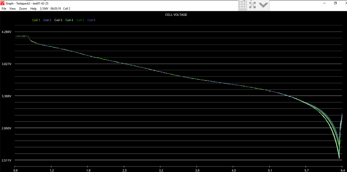
But more importantly, you should research Tesla discharge graph more. There’s very little to gain in terms of capacity in going with low voltages, Jack shared that too:

https://youtu.be/HIAIX3oEHZs

0 Likes 0 ·
Rob Duthie avatar image
Rob Duthie answered ·

Hi All

You have to have the right number of cells in series to get the correct voltage to suit the inverter that is a matter of fact. Get that right and the inverter will perform as designed and intended.

If you buy a standard lithium battery module rated to 12v it will will have the correct number of cells to make up the 12v, so using Tesla and leaf batteries, you are on your own, if you are not wiring them up correctly, don't complain about the inverter!!!

For 12v you need 4x in series

For 24v you need 8x in series


Regards

Rob Duthie

Rotorua

New Zealand

6 comments
2 |3000

Up to 8 attachments (including images) can be used with a maximum of 190.8 MiB each and 286.6 MiB total.

Jay Kote avatar image Jay Kote commented ·
  • This is not a criticism of Victron, but Victron must be held to its promised specifications
  • They say the inverter will work to 19v and it does, only once it goes off, you cannot turn it back on unless it is above 21.5v
  • This is a software bug, because if the problem was victron hardware then as soon as volts dropped below 21v, it would stop working.

What has been suggested is to leave the inverter on, that is a good work around to the problem for moment.

But of Victron wants to be consider top brand name, software bugs need to be FIXED not whited washed the way cheaper inverters deal with these issues -- its easy to tell customer who spends 600 - 700 on 3000W inverter that has these problems, "you get what you pay for."

But when a customer buys Victron brand and they have paid almost $2000, its hard to say and not be embarrassed.

Victron Software Team needs to step up and fix this and Victron Sales & Victron Hardware engineers need to press the attention on this customer embarrassing situation.

Field techs like me want to support what so far seems to me to be a good product line, but Victron Sales and Engineering has to do its part to ensure that we can.

2 Likes 2 ·
geomz avatar image geomz Jay Kote commented ·

Some of those units cost way north of $2K. And by the time you implement all the little doodads that go with it, color control, bmv, Venus gx, yada yada; break out another thousand +.

And these "homebrew" solutions are only going to become the norm. Tesla batteries, in (not just) my opinion, are far superior to many other technologies, and at their price point will likely eclipse other solutions quite rapidly -they kinda already are. Just search YouTube.

Not to mention Nissan Leaf, and chevy volt, and and and.

It really seems that lithium is (still) an afterthoght on these units. I see minimal-to-no point in the "Lithium" checkbox on the inverter. That might be a good place to implement substantive controls/settings.

I really genuinely like Victron equipment. And it's fantastic when it works. But when all the bits and pieces come slamming backwards, the response I unfortunately hear often is... yup, deal with it.

Which runs completely counter to what's clearly being tried here with a forum to share ideas and a modifications section for users to share solutions, etc.

It's my hope that Victron is heading more toward faster and more timely responses to customer issues. They have a vast wealth of "beta" testers more than willing to "break" things... for science :)

1 Like 1 ·
Jay Kote avatar image Jay Kote geomz commented ·

To be honest, i would have gone with Magnum/Outback/MidNite solar. Not because I have a brand preference. Just new to Victron. My customer wanted Victron because of the color controller. They saw it in another install and want it.

If I could get the Victron Color controller to work with Magnum, I would used those as I know this pesky 22v 6S thing is not a problem with Magnum (at least according to Magnum). I am now looking to see if I can use Magnum with Color Control. I guess I will have to post here.

Also, I am waiting for my customer to find out if (a) the person who made the custom battery will either take it back or change it for them from 6S to 8S (even for a fee). He told me it was sold as is and no refunds. So, I'm doubtful. (b)And if they are going to live with the situation of only 50% use, if stuck with 6S. I'm trying to remain unbiased, as it is a sure way to loose a customer not to give them what the want.

1 Like 1 ·
geomz avatar image geomz Jay Kote commented ·

I know what you're saying. And those things (tesla batts) are sold almost perfectly suited for a properly functioning 24V system, without any "modification".

So I don't think you or your client have done anything wrong. But I get it, sometimes you just gotta get business done :)

When Victron's stuff works, it works quite well. But when stuff like this happens, it leaves one wondering.

I'm looking at an almost identical solution (with tesla batteries) and I'm very disappointed by this development.

Did you see my other post about juking the v-sense wires against a "fake" voltage input to see if that'll wake it up? Might not be a solution to leave a client with, but it could be setup with a switch that would flip the contacts temporarily, to prime it like some dusty-old-diesel, to wake it up, and then flipped back to "normal" for operation.

Either way, good luck!


0 Likes 0 ·
Jay Kote avatar image Jay Kote geomz commented ·

I have not seen it. I'll have to look into it. If I have to "rig" something I guess I will have to "rig" something -- My customer is anxious not to lose their money on the 6S battery they had built for them.

0 Likes 0 ·
geomz avatar image geomz Jay Kote commented ·

Just as an FYI, they really don't "build" anything for these modules. They come, ready to roll, as is, in 6s-cell modules and are physically built to be operated within the stated voltages above. In a tesla these modules are then made into further s and p configuration to raise the operating voltage to ~375 volts.

Making them any other level of cell configuration takes considerable effort and risk of fraking it up royally :)

It can be done, and others have done it, but it's not a solution most aim for, since out of the gate, they're perfect for a 24v system -at least one that's working correctly anyway :)


0 Likes 0 ·
boekel avatar image
boekel answered ·

Have to add something to that:

LiFePO4 batteries: 4s for 12v, 8s for 24v, 16s for 48v

Lithium Ion batteries: no solution for 12v, 7s for 24v, 14s for 48v

You can make it work with 3s / 4s for 12v, 6s or 8s for 24v, and 12s to 16s for 48v, but with limitations.

limitations:
with 3s / 6s / 12s the inverter doesn't start below 30% SOC, (3,6V is about 30% SOC, 3,3V is almost empty, 4,2V is 100%)
with 4s / 8s / 16s you can't charge above 4v per cell, something that misses the top 25% SOC, but increases battery life greatly.

When using the Tesla batteries in an ESS system, you never shut down the inverter, and don't have the problem of not being able to start belof 30% SOC

So using the inverters 'out of spec' has limitations, but at least it works!

2 |3000

Up to 8 attachments (including images) can be used with a maximum of 190.8 MiB each and 286.6 MiB total.

oxy avatar image
oxy answered ·

@rockatron it seems you have found a bug. Have you contacted Victron support? Did they indicate a possible firmware patch?

2 comments
2 |3000

Up to 8 attachments (including images) can be used with a maximum of 190.8 MiB each and 286.6 MiB total.

Tom avatar image Tom commented ·

@rockatron @oxy-

I talked to a victron tech and the firmware is set up is your SOC is below 21.8 volts the mulitplus inverter side will not turn on until you charge up your battery. If you have your mulitplus on and SOC at 22 volts you can operated the inverter down to 19 volts as long as you do not shut the inverter power off.

It is not an inverter limitation, but a software firmware limitation set up deliberately. Victron has not considered other battery options like the Tesla battery.

1 Like 1 ·
Rob Duthie avatar image Rob Duthie commented ·

You have to have the right number of cells in series to get the correct voltage to suit the inverter that is a matter of fact. Get that right and the inverter will perform as designed and intended.

If you buy a standard lithium battery module rated to 12v it will will have the correct number of cells to make up the 12v, so using Tesla and leaf batteries, you are on your own, if you are not wiring them up correctly, don't complain about the inverter!!!

For 12v you need 4x in series

For 24v you need 8x in series

Regards

Rob Duthie

Rotorua

New Zealand

-2 Likes -2 ·
Jay Kote avatar image
Jay Kote answered ·

I have a similar situation for a customer who bought a custom 6s battery which was sold as 24v. Not sure what to tell my customer cause it would mean they can only use 50%.


I think vuctron needs to put out a sw patch Otherwise, we are in process of ordering and will have to see if I need to advise customer to go non-victron. Have 2 weeks.

2 |3000

Up to 8 attachments (including images) can be used with a maximum of 190.8 MiB each and 286.6 MiB total.

oxy avatar image
oxy answered ·

Have you tried contacting Victron support about this SW behavior? It would be interesting to know their response.

Does the problem appear only when you (a) turn off inverter manually below the mentioned voltage or (b) it reaches the low cut-off voltage and powers off? In other words, if you use the system as always-on and with a sufficiently charged battery it works fine?

BTW, feels worth mentioning that even on lead-acid MultiPlus won’t always power back on automatically after reaching the cut-off voltage. There’s some limit of retries it will perform, after which even if your battery becomes fully charged you may need to go and restart it manually. Granted, it does power on as the voltage is higher than the one in the thread above.

2 |3000

Up to 8 attachments (including images) can be used with a maximum of 190.8 MiB each and 286.6 MiB total.

geomz avatar image
geomz answered ·

That's a pretty sucky deal and makes absolutely no sense that this limit is being arbitrarily applied.

I think you may be down to "hacking" a workaround.

On my Quattro, I can turn on my unit, even if I have the battery switch turned Off (i.e., batteries completely gone and out of the picture) as long as I have mains power on (generator, shore, etc).

If mains power is not an option, I still think there may be value in trying this,

Connect your v-sense cables to a voltage higher than this arbitrary (and buggy) value (using a drill battery or something similar) and see if that will turn on the unit.

Put things back the way they should be and try not to power the unit off with voltages below the bug limit until Victron sees fit to fix the bug.

It may not be ideal, but might help you awaken the sleeping thing enough to get back to business.

Also, I'm not certain what impact a BMV would have in this equation -if it's also reporting the low voltage to the inverter. So it may need to have power removed (by pulling the positive terminal connector out).

Not sure it'll work, but hope it helps :)


4 comments
2 |3000

Up to 8 attachments (including images) can be used with a maximum of 190.8 MiB each and 286.6 MiB total.

geomz avatar image geomz commented ·

Also, my Quattro will NOT power on, regardless of mains or battery status, if I have my CCGX connected and (presumably because) not powered. My CCGX loses power when the inverter is off. It's a left-over from the old 12V system that I haven't rewired yet. So I have to unplug (RJ45 plug) it to power on the unit.

But anyway, something else to consider. Not likely your situation as you've pretty much narrowed in all-around it, but... :)

0 Likes 0 ·
Rob Duthie avatar image Rob Duthie commented ·

Hi All

You have to have the right number of cells in series to get the correct voltage to suit the inverter that is a matter of fact. Get that right and the inverter will perform as designed and intended.

If you buy a standard lithium battery module rated to 12v it will will have the correct number of cells to make up the 12v, so using Tesla and leaf batteries, you are on your own, if you are not wiring them up correctly, don't complain about the inverter!!!

For 12v you need 4x in series

For 24v you need 8x in series

Regards

Rob Duthie

Rotorua

New Zealand

0 Likes 0 ·
geomz avatar image geomz Rob Duthie commented ·

With all due respect, we can argue for the "right number of cells in series" all day - 4s, 5s, 6s, 876,453s, but the facts are:

1) voltage is voltage

2) the unit is rated, speced and sold for 19-33V.

3) It will happily continue drawing from the batteries to well below 20V.

4) By my math 21.8v (the OPs original and repeatedly stated voltage) is greater than 19v and 20v.

5) the statement of using tesla batteries you're "on your own" is wildly tangential, counterproductive, and annoyingly dismissive.

6) your math of Xs is based purely and mostly arbitrarily on the perception of ONE chemistry. Different chemistries will have completely different voltages and thus different Xs configurations.

Regards

GM

1 Like 1 ·
Jay Kote avatar image Jay Kote commented ·

Just saw this ... pretty good hack. Might work. You might need two in series cause, at least in US, most tool batteries are 18 or a pseudo 20v.

0 Likes 0 ·
geomz avatar image
geomz answered ·

@rockatron, will the unit not power on even if mains power is applied?

2 |3000

Up to 8 attachments (including images) can be used with a maximum of 190.8 MiB each and 286.6 MiB total.

mvader (Victron Energy) avatar image
mvader (Victron Energy) answered ·

Hi all, thank you for bringing this up. I'll discuss it with the software engineer that knows the details behind this; and post back here.

33 comments
2 |3000

Up to 8 attachments (including images) can be used with a maximum of 190.8 MiB each and 286.6 MiB total.

mvader (Victron Energy) avatar image mvader (Victron Energy) ♦♦ commented ·

Hi all, just an update that we’re planning an improvement.

I’ll keep you posted. Unfortunataly, I can’t share any details yet, we don’t know yet whats possible and whats not.

0 Likes 0 ·
Tom avatar image Tom mvader (Victron Energy) ♦♦ commented ·

This would be great even if the firmware can be adjusted to 20 volts minimum charge to turn on the unit. My charge range is 19 volts to 24.4 volts.

0 Likes 0 ·
Jay Kote avatar image Jay Kote Tom commented ·

Friend of a friend of a friend told me that Victron has no intention to fix the problem. I don't know if it's true. Apparently, this is considered "hardware limitation." But as I said, I cannot confirm.

Only sharing it in hopes someone else can give definitive answer. As I said, I have a customer who needs this to work and if it doesn't I'd rather be able to tell them sooner and not later.

They already seem ready to walk away from this -- it's $5,000+ they are looking to spend and rather then they walk away, I would rather be able to sell them something different that will solve their problem. If someone knows of a way to hook the Victron Color Control to another inverter, please let me know.

0 Likes 0 ·
Guy Stewart (Victron Community Manager) avatar image Guy Stewart (Victron Community Manager) ♦♦ Jay Kote commented ·

Hi rvsolartech,

Perhaps you did not know, but Matthijs (mvader) is the owner and CEO of Victron. He has said just above that he is planning an improvement, and is looking into what is possible and will keep us posted.

If he had no intention to fix it, he would say so and that would be the end of it.


0 Likes 0 ·
Tom avatar image Tom Guy Stewart (Victron Community Manager) ♦♦ commented ·

That is great news. Just my opinion there are many used 444 5.3 kw battery modules available to use as storage devices at very cheep prices and as these cars age more will hit the market.

I installed the 24/3000 120 volt Multi plus and two Victron BMS in my system. From my research I found the Multi plus to be the most adjustable to newer technology batteries.

0 Likes 0 ·
Jay Kote avatar image Jay Kote Guy Stewart (Victron Community Manager) ♦♦ commented ·

No as a matter of fact I did not know. But perhaps he has not been informed that others have concluded it cant be done.

Is it not harder for the parent to accept a childs flaws then others?

Im new to victron have always used magnum and once OB. But I have a customer who is keen to use victron color control and I couldnt not figure out how to give them color control and magnum (which does not have this issue). So Im anxious as they will not let me start project until this is resolved.

Even if the word is it wont work, then at least I can possibly get them to give up their requirement for Color Monitor.

Because magnum at same price is 4000VA, not 3000VA, is pure sine, and is also hybrid.

So I can get going and get paid once I get word on this. But they wont let me move without this answered. So Im anxious.


(They arent even letting me order the other stuff eg bvm, mppt, etc.)

0 Likes 0 ·
boekel avatar image boekel ♦ Jay Kote commented ·

It's not a flaw, it's designed for Lead-acid batteries and now used out of spec. And still working good for most systems.

With big installations (on and off-grid) there is no problem at all, only some mobile installations cannot power up at low SOC.

Big installations typically never shut down: no problems
grid-tied installations typically never shut down, and/or have grid supply to start up: no problem

off-grid with backup generator: no problem


only problem: small systems without AC-input, when SOC gets too low and no solar to support.

My biggest system: 60kWh 12s lithium system, no problems.

0 Likes 0 ·
Jay Kote avatar image Jay Kote boekel ♦ commented ·

The goal of a business is to make a product that satisfies the needs of as many customers and functions as good or better than competition.

So to you the problem that software cannot be changed and some units are not same quality resulting in loss of sales is not a flaw? -- yours is the superior intellect

0 Likes 0 ·
Show more comments
Tom avatar image Tom Jay Kote commented ·

@rvsolartech becareful with choosing the Magnums hybrid or xantrex freedom inverter when using a tesla battery. Both I believe have low power shut down at 20 volts. The Multi plus is 19 volts. 20 volts really limits the SOC of the tesla battery. Also the victron color gx really is not useful in a RV. $500 for an on off switch. You would be better with the $300 Venus gx giving you Bluetooth and tank levels and relay to program start a generator. Use a color tablet to control it.

If you are concerned about limiting the lower end of the usage of the tesla module, you can add a second one if you have the space for $1200 and bring you capacity to 8Kwatts. Or you can spend more for Battle Born Lifepo at 4 times the cost but get full capacity out of the battery.

Maybe Victrion can created a Tesla 6S profile within the charge software to allow for the lower voltage shut off so as not to interfere with lead acid profiles. I would be happy to allow my 24/3000_120 set up with one tesla 444 module for testing if they can do it in Florida. Tom

0 Likes 0 ·
Jay Kote avatar image Jay Kote Tom commented ·

I dont control what my customer wants. For whatever reason they really liked color monitor in another RV solar setup.


Magnum has low voltage and restart programmable to 18v.

I will explain to my customer they will loose 50% of 6s battery with victron and that color monitor is too much anyway for RV as you said. (Ive never used it.)


But magnum has programmable low cutoff to 18v and requires restart of 18.5v-18.75v. So this is perfect: 19.5v cutoff & 20v restart.


Also it means I can give them two AC supplies wo installing a transfer switch like I would have had to with multiplus.

And now that Ive got reason, I can also get them to use comparable quality mppt at lot lower price. Was forced to use victron mppt cause of color monitor.


I can save them $1500 - $2000 using magnum and non-victron mppts, bvm, etc as this was needed to mk color monitor work.


I think they will be disapponted not getting color monitor, but with victron owner saying no support for 6s will make it easier to offer magnum and non-victron option now.


1 Like 1 ·
Show more comments
tededd avatar image tededd mvader (Victron Energy) ♦♦ commented ·

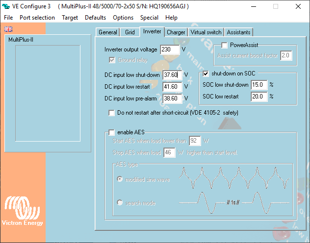
I haven't tested yet as require some large loads to empty the battery bank, but noticed in the settings the for the low battery and low restart can be set to % instead of voltage. My BMS is the master and provides the Victron with SOC as percentage (based off voltage).

Though very keen to see what progress can be made with available settings :)

0 Likes 0 ·
oxy avatar image oxy tededd commented ·

Where did you find the % settings? VE.Configure?

0 Likes 0 ·
tededd avatar image tededd oxy commented ·

Currently my Mac so can't access the software but see the link for the page of VE config (though options not shown in this pic!)

On the version I have there is a section ninth space to the right of the DC low voltage cutoff settings.

Greyed out until you check the tick box.

https://www.victronenergy.com/live/_media/drafts:sa_system:veconf-inv.jpg?w=440&tok=ee06e4

0 Likes 0 ·
Jay Kote avatar image Jay Kote tededd commented ·

It looks like this is a European model and you do not have the problem as with the 24V US model. Very likely that Victron does not sell the same quality in US as in Europe.

0 Likes 0 ·
ben avatar image ben ♦ Jay Kote commented ·

I run both 120V and 230V units, and mine work the same. Why would they want to make an inferior product for one market?

The SOC-based cutoff is a new software/firmware feature.

0 Likes 0 ·
Jay Kote avatar image Jay Kote ben ♦ commented ·

I dont know. But I do know that 110v is targeted to US and 230 Europe.

So the hardware is indeed different.

I have been thinking that if this 230v version can be reset to work below 21.8, and US cant (as others report) then the quality of product is not the same.

I dont have a unit, but looking at the OP reply showing that he had control on this thread lead me to believe he is able to get his 230v unit to work.

And I was more inclined to think that when I heard there would be no fix because of a hardware problem.

0 Likes 0 ·
Show more comments
oxy avatar image oxy tededd commented ·

I’m not sure I understand the setting you are reffering too. Maybe you can make a screenshot with camera, assuming it’s difficult to transfer one to your Mac?


BTW, what firmware version your inverter is on?


Thanks!

0 Likes 0 ·
boekel avatar image boekel ♦ oxy commented ·

the SOC settings won't help you, the voltage limit will still be active. And for lithium batteries the voltage limit is usually the better setting.

0 Likes 0 ·
steveca avatar image steveca mvader (Victron Energy) ♦♦ commented ·

From a business perspective, The future will see an enormous quantity of used Tesla battery modules coming to market. Tesla battery modules are state of the art, except that they are 6S. I would encourage your company to facilitate their re-use as it represents a huge untapped market as we shift from lead acid ESS to recycled lithium based EV car batteries. I personally know quite a few folks looking to build home powerwalls using Tesla battery modules along with your products for seamless integration with their solar systems and the grid.

In addition, you could tout your company' role in enabling the future of second life ESS growth which is great for the environment and your bottomline.

I personally love your products and its customization potential (critical for use with varying Lithium chemistries) and hope to see you guys lead with products that will facilitate sustainable re-use as opposed to recycling of the trillions of lithium cells currently in existence.

0 Likes 0 ·
Tom avatar image Tom steveca commented ·

Agreed. The Tesla 6S444 module has the highest energy density at the lowest cost. I bought mine at $1100 each. Using it with the Victron 24/3000 120USA inverter. My work around with restart at 21.8volts is just to run my generator for a bit and turn on my Multi Plus.

Charges at 30 amps currently, but how do I charge at 50-70 amps if the unit can only be connected at 50 amp service max? Currently my shore power plug is 30 amps. I can use a dog bone to connect to 50 amp service.

0 Likes 0 ·
steveca avatar image steveca Tom commented ·

70 amps charging at 25 volts equates to 1750 watts. A 30 amp shore power AC source at 120 volts can supply 3600 watts. You should have no problems charging 24 volt batteries at 70 amps when supplied with 30 amps of 120 volt AC.


Remember, 70 amps at 24 volts is far less power than 30 amps at 120 volts. Volts X amps equals wattage.

0 Likes 0 ·
Tom avatar image Tom steveca commented ·

Thank you. I will be looking at changing my charge profile when I install the new software. Higher amp charging means faster charging.

0 Likes 0 ·
steveca avatar image steveca Tom commented ·

You are welcome. I am very pleased that I will now be able to use the quattro in my Sprinter van build with two tesla modules for over 10KWH of battery storage! Ive held off on it until the recent update by Victron.

0 Likes 0 ·
Jay Kote avatar image Jay Kote commented ·

I understand you are the head of Victron from a Victron engineer. I'm pretty impressed that an executive at your level is taking a personal interested in this. And is as knowledgeable as you are.

Shame more executives are not as knowledgeable about the intricacies of their own products like you.

Vast majority of executives only understand their products at a financial level. Many even pride themselves as being "widget" managers because of their MBA training. Never felt this was a good thing.

So glad you are at the helm.

0 Likes 0 ·
mvader (Victron Energy) avatar image
mvader (Victron Energy) answered ·

Hello all,

Previous answer removed - See updated answer - this has now been improved.


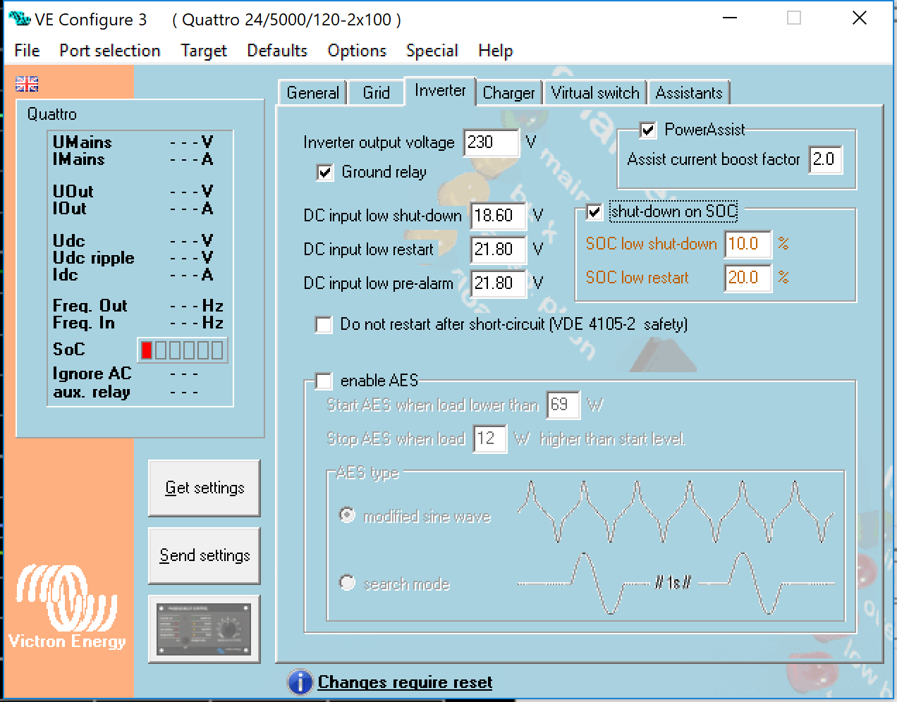
The related topic as discussed in these threads: yes we added shutdown on low SOC some time ago. See VE.Bus firmware change log. However that does not lower any DC voltage shutdown limits. see also below screenshot.


Thanks all for all the effort and input!


Best regards, Matthijs


4 comments
2 |3000

Up to 8 attachments (including images) can be used with a maximum of 190.8 MiB each and 286.6 MiB total.

Rob Duthie avatar image Rob Duthie commented ·

Hi

As i have being saying all along, use the the correct series battery configuration to suit the inverter not skimp by using 6 in series. when it should be 7 to 8 in series.

0 Likes 0 ·
tell-me-more avatar image tell-me-more Rob Duthie commented ·

Very hard to do 7s or 8s in series with a tesla model s module ....

0 Likes 0 ·
tell-me-more avatar image tell-me-more commented ·

This is unfortunate, Has anyone found a viable work around?

0 Likes 0 ·
Jay Kote avatar image Jay Kote tell-me-more commented ·

There is a work around, I offered it to a prospective customer, they did not like one or the other, but chose one they could live with.


First work around was to start the generator until the battery voltage reached 22v or 23v (forgot now what it is minimum).


The second was I install another manufacturers inverter. They didnt like that because they wanted to use the color monitor as the plan was to go solar after the inverter/ monitor was working using all victron products.


(It was too much money to get venus to work with the other inverter.)

Victron announced they have no immediate plan to fix this issue as it is hardware and software problem.

So between the two they opted to give up on color monitor and went with other manufacturer. They also decided to postpone the solar. Shame cause I was looking forward to it.


0 Likes 0 ·