Hi,
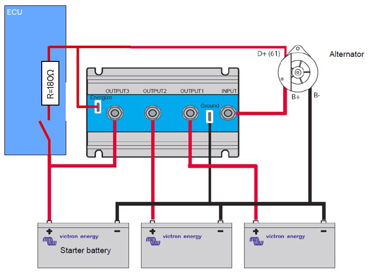
I adopted my engine with an Argofet 200-2, so that I can charge 2 different battery packs. Unfortunately I can't install the Argofet as proposed in the specification, as the ignition switch and the resistor is integrated in my engine control unit.
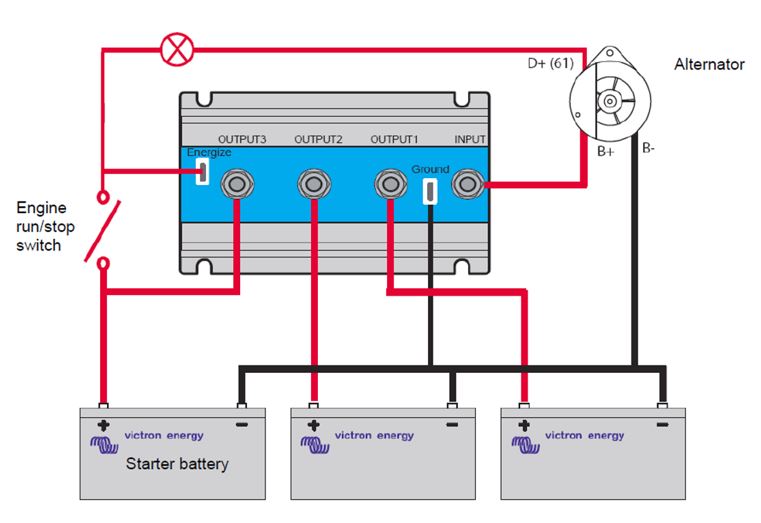
As proposed in the Victron datasheet:

My System looks like this:

I know that my alternator needs dc voltage at B+, therefore I used the energize Input. Unfortunately this energize input doesn't work in my system and the alternator is not charging and producing voltage. Why has the resistor / lamp to be between Engergize Input and D+?
While testing I accidentaly interrupted the ground cabling from the Argofet. Funnily without ground, everything works fine, but I doubt that's the ideal solution.
Does anyone know how the ArgoFET looks like / works in detail and what could be the reason for the malfunction.
Thanks a lot
Niklas
