question

jwfrary avatar image
jwfrary asked

Multiplus in Parallel with two different AC inputs

https://www.victronenergy.com/upload/documents/7-PHOENIX-MULTI--2-AC-INPUT.pdf

I noticed this schematic, but couldn’t find any documentation as to how is would behave in this configuration.


at the moment I just have both feeds into a changeover switch. I’m wondering how it would then differentiate between the two power sources does the one to the slave become ac input 2 on the CCGX?


could someone point me in the right direction if there’s some documentation I have missed!

Thanks

MultiPlus Quattro Inverter Charger
1 comment
2 |3000

Up to 8 attachments (including images) can be used with a maximum of 190.8 MiB each and 286.6 MiB total.

jwfrary avatar image jwfrary commented ·

If I went to this I would likely just remove the jumpers from the back of the changeover switch I have already so I would never have both sources connected at the same time, just switching one source to the master and a second to the slave.

Although the schematic seems to suggest that’s fine!? Not something I thought you could do. Hence my question!

The other question with it is how does the battery charging function behave in this configuration. If your only using one ac input to one inverter does that reduce your charging current but retain the inverter capacity for power assist from both?

0 Likes 0 ·
3 Answers
Margreet Leeftink (Victron Energy Staff) avatar image
Margreet Leeftink (Victron Energy Staff) answered ·

This schematic is quiet old. it is from before the time we had the Quattro.

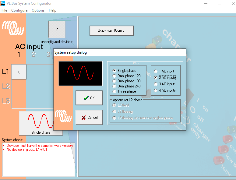
In the schematic, one AC source is connected to Multi 1 and the other to Multi 2. They then are set up as a "special" parallel pair with using VE.Bus System Configurator software. As soon as one of the AC in sources is active it will be used for charging and feed through. But, there is one downside to this, when in charger mode, only one of the charge sources can be used. So only one of the Multis is charging or transferring AC. you will loose the capacity of the other Multi. But when inverting mode both Multis work together in parallel.

A better solution is to use an external transfer switch. this way both units are used during charging and inverting.

Or use a Quattro, it already has a build in transfer mechanism :-)


2 |3000

Up to 8 attachments (including images) can be used with a maximum of 190.8 MiB each and 286.6 MiB total.

jwfrary avatar image
jwfrary answered ·

Hi,

Thanks @Margreet Leeftink (Victron Energy Staff) for your reply.

I assume the 'special setting' pictured below (Appreciate there are more steps to it) is the one you are talking about.

Would the colour control GX then realise there is two AC's and then tell you which one you are connected to? Or is that purely reserved for Quattro?

The charging actually isn't much of an issue for us as the multi's are set to 75% circa 100 amp between them; now anyway so 70amps from one won't be a problem since the alternators on the main engines will top up the difference most of the time anyway and the soon to be fitted MPPT as well. Indeed we are likely to run with the generator off quite a bit. The reason we have two 3000's is to supply our UPS load if we lose the generator (max UPS loads of around 4000watt) but at a higher temperature (thinking of those hot summer days) with a bit of redundancy to boot.

I presume we would retain the power assist feature from both multi's where the existing Gen is 7.2kva and so we get around 11kva theoretically in the current config.

I have to make the system really foolproof and therefore someone looking at a CCGX display that's telling them the powers coming from the shore when it's actually coming from the gen could cause confusion down the line. It's also why I'm not too fussed about huge charge rates.

It's all fitted on a 12m Commercial Power Catamaran, outfitted in all Victron gear, products which we really believe in and feel we can trust.


2019-12-24-2.png (70.2 KiB)
2 |3000

Up to 8 attachments (including images) can be used with a maximum of 190.8 MiB each and 286.6 MiB total.

jwfrary avatar image
jwfrary answered ·

Ok, so I have run the system up today. All works!

Apart from when the second AC input is energised and the ac1 is off I was expecting to CCGX to display this, instead the red box just goes blank.

The multi control panel displays the power as coming from AC2.


is this a feature or is there some configuration setting I’m missing?

Thanks.

Relay is set to generator but I haven’t yet got that wired up

15 comments
2 |3000

Up to 8 attachments (including images) can be used with a maximum of 190.8 MiB each and 286.6 MiB total.

Unfortunately a GX device cannot show the incoming current correctly with such a setup, due to the way the VE.bus protocol works.

Why have you not used a Quattro for this?

0 Likes 0 ·
Show more comments