question

Jafa Russell avatar image
Jafa Russell asked

Argofet and MPPT compatibility question

HI guys,

Can someone with expertise with the Argofet help me, I want to add an Argofet to split charge my VRSLA start battery and my LFP house bank. Easy so far. I want to connect an MPPT controller to the input of the FET and utilize the alternator energize circuit to tell the MPPT that there is voltage. The solar controller needs to see voltage at the battery terminals or it wont start charging.

This is what I had in mind, will it work?
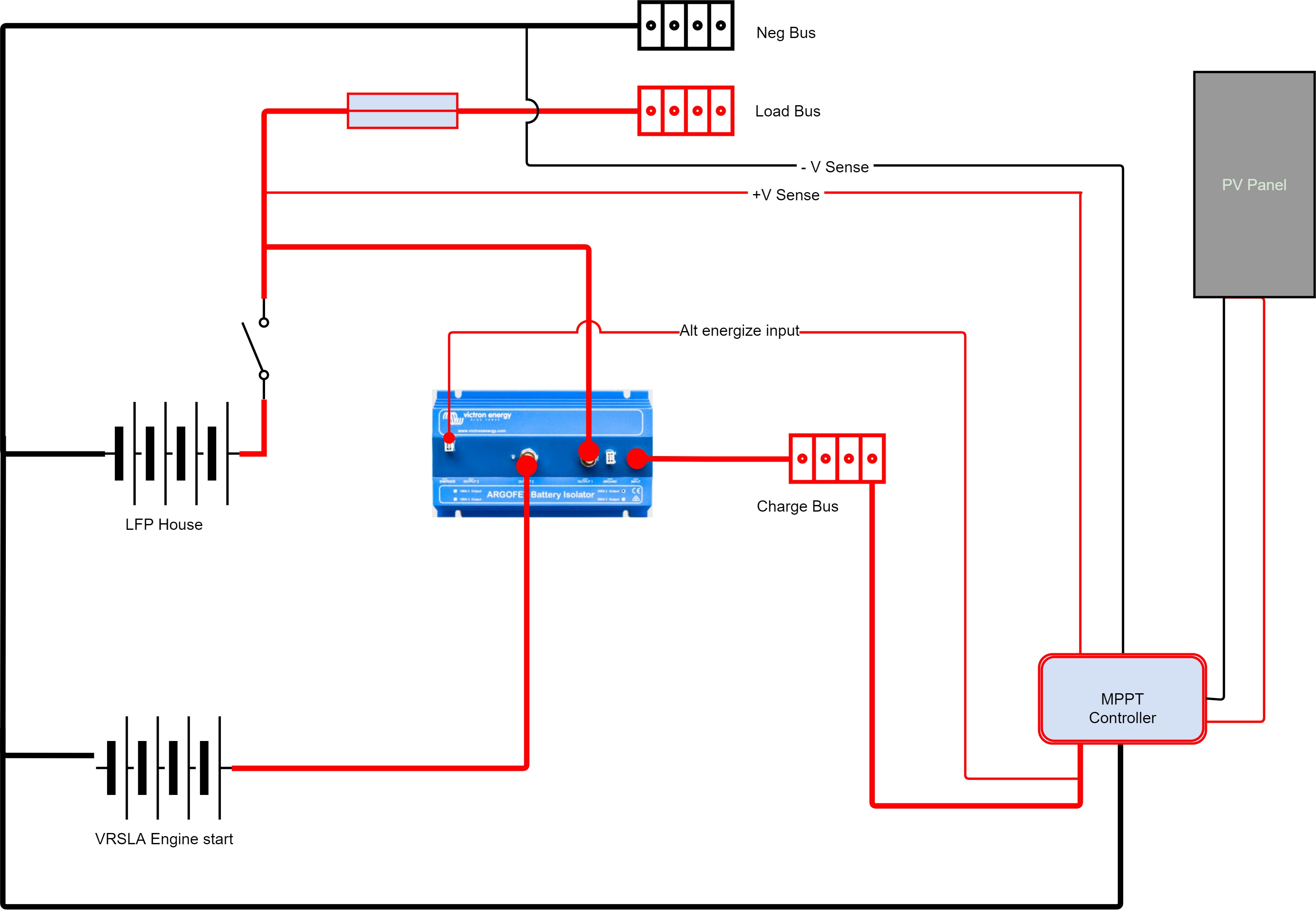

The following is from Victron ArgoFet documentation...


Alternator energize input
Some alternators need DC voltage on the B+ output to start charging.
Obviously, DC will be present when the alternator is directly connected to
a battery. Inserting a Diode or FET splitter will however prevent any
return voltage/current from the batteries to the B+, and the alternator will
not start.
The new Argofet isolators have a special current limited energize input
that will power the B+ when the engine run/stop switch is closed.

MPPT ControllersSolar PanelalternatorArgo FET Diode
argofet-maybe.jpg (298.4 KiB)
1 comment
2 |3000

Up to 8 attachments (including images) can be used with a maximum of 190.8 MiB each and 286.6 MiB total.

kogir avatar image kogir commented ·

@Jafa Russell Did you end up doing this? How well has it worked?

I find myself in a similar position where I have three isolated batteries I'd like to charge from both my SmartSolar charger and a Buck/Boost DC/DC converter powered by an alternator.

If I could start again I'd have a single battery bank but it's too late now.


0 Likes 0 ·
3 Answers
Justin Cook avatar image
Justin Cook answered ·

@Jafa Russell, I will add something here that I can add because I'm not Victron staff so I can -perhaps- play a little bit more with non-supported connections, although I will re-emphasize the not-supported part, and state right up front that I do not recommend doing this:

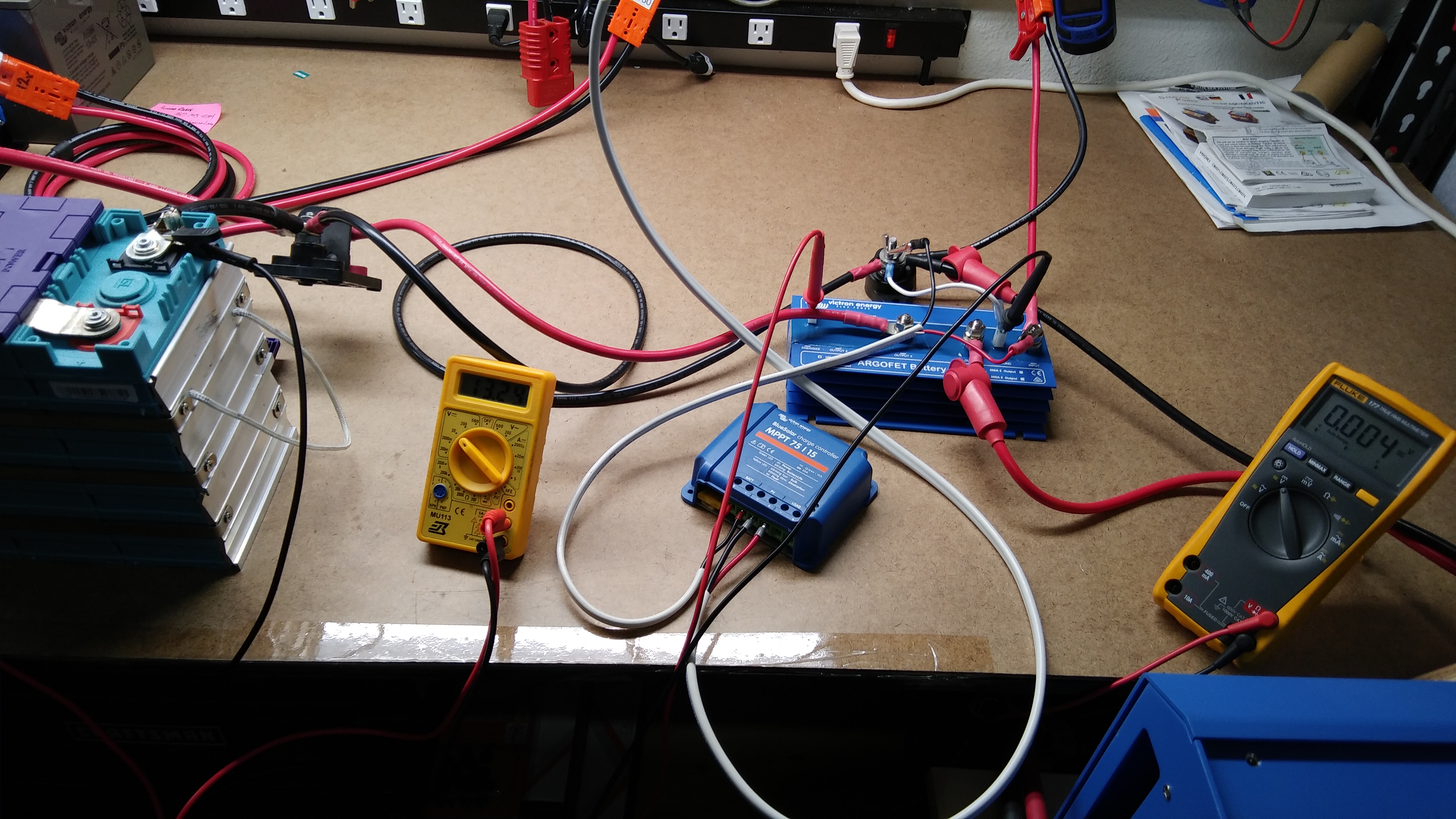
The MPPT does not need to see battery voltage to turn on; it will turn on based on PV voltage, and shortly after it turns on it will -on its own- apply enough voltage through its battery-out terminals to wake up the ArgoFET (the ArgoFET needs ~8v at the alternator input to turn on) and will then, after ~45 seconds delay, start charging through the alternator input to the batteries connected to the outputs. Thus, you do not actually need to use the energize alternator input at all for this to technically work; the positive "battery" connection from the MPPT can be connected to the "alternator" input of the ArgoFET and the negative battery connection can be connected to the common NEG shared by the ArgoFET, the batteries, and etc.

I know this only because I was curious enough to go replicate and document the behavior on my test bench.

Two caveats that I can immediately identify:

1. The MPPT history and metrics will be messed up because it's shutting all the way off, and starting back up from 0v at the "battery", which normally is a condition that it would never see. Feeding the energize input with 12v will keep the MPPT "alive", which would solve that issue, but it also keeps the ArgoFET alive, thus adding a certain amount of self-consumption that you would need to figure into your calculations. On my test bench, the ArgoFET 200-2 and the BlueSolar 75/15 together draw ~0.05A in total to keep themselves awake.

2. This is, as pointed out, not an approved connection, and therefore you'd be on your own if something doesn't work right or goes wrong and drains your batteries or damages the device itself. As soon as you start connecting things in other-than-approved manners, your warranty and service options pretty much go out the window, so -again- I do not recommend this connection even though in testing it does appear to work perfectly well.


1 comment
2 |3000

Up to 8 attachments (including images) can be used with a maximum of 190.8 MiB each and 286.6 MiB total.

Jafa Russell avatar image Jafa Russell commented ·

@Justin Cook, Brilliant, Thanks for doing the testing, and posting such a comprehensive answer, really appreciate the effort

0 Likes 0 ·
Daniël Boekel (Victron Energy Staff) avatar image
Daniël Boekel (Victron Energy Staff) answered ·

Hi @Jafa Russell

This is not a supported configuration, please just connect the MPPT to the battery.

charging the starter battery can be done for example with a dc-dc converter.

2 comments
2 |3000

Up to 8 attachments (including images) can be used with a maximum of 190.8 MiB each and 286.6 MiB total.

Jafa Russell avatar image Jafa Russell commented ·

Hi @Daniël Boekel (Victron Energy Staff)

Thanks for the reply, although not the news I wanted to hear :)

I know I could just connect the MPPT to the charge bus and then charge VRSLA with a dc-dc, but that configuration doesn't allow for a safe disconnect of the LFP bank in the event of an issue, ie charge sources will have no battery in the circuit, resulting in component destruction, alternator diode pack, likely failure of the MPPT etc.

The above configuration note that the charge bus still feeds into the positive bus after the lithium bank has been disconnected. The voltage from the charge bus is limited by regulation and the presence of the lead-acid battery, but the power quality may not be perfect. In such a configuration, it is very important that the lead-acid battery always remains present in the charging path. A battery switch to isolate the engine circuit is fine and desirable, but the charge isolator(s) should remain directly connected to that battery at all times to provide a pathway to dissipate any surge, as well as a nominal base load for the charge regulators.

Can you give me a more in depth and technical reason for the Argofet not being suitable please, "not a supported configuration" doesn't satisfy my curiosity :):)

0 Likes 0 ·
Daniël Boekel (Victron Energy Staff) avatar image Daniël Boekel (Victron Energy Staff) ♦♦ Jafa Russell commented ·

you could connect the lead-acid battery directly to the MPPT and the LFP bank through the argofet?

You didn't mention the alternator before, the same applies to that.

you can create all kinds of possible solutions, but we cannot support every possible solution.

if you use an alternator connected to a lithium battery, best practice is to switch off the alternator when the BMS detects an error, it depends on the alternator regulator if and how this can be done.

0 Likes 0 ·
pim avatar image
pim answered ·

Hello Jafa, did you find a good solution at the end? I've got the same question...

2 |3000

Up to 8 attachments (including images) can be used with a maximum of 190.8 MiB each and 286.6 MiB total.