
Isolation Transformer 3600W
Has anyone else had this problem
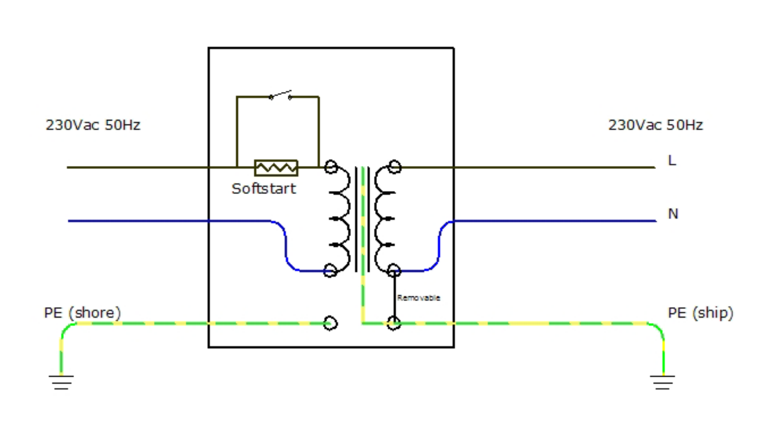
would be nice if I could get a full circuit diagram
but to my understanding there should be no electrical path between Boat PE and shore
This site is now in read-only archive mode. Please move all discussion, and create a new account at the new Victron Community site.
Isolation Transformer 3600W
Has anyone else had this problem
would be nice if I could get a full circuit diagram
but to my understanding there should be no electrical path between Boat PE and shore
Are you measuring between shore and boat? or the isolation transformer itself?
measuring between shore and boat you do on voltmeter position, not resistance.
Try unplugging shore-power, resistance or voltage should remain the same.
Hi Daniel
Could you possibility of sending me a circuit diagram
I had a Volt reading of 0.018V AC across the two earths
My I add that when unplugged from the shore line it reads open circuit
Any help is most welcome
Hi @Neil JB
So where did you measure this time? especially with shore-power unplugged?
there should be a reading with shore-power unplugged, between the shore-power earth and the boat's earth, either voltage (expected) or at least a resistance.
If not: please get an electrician involved to check your wiring / shore-power wiring.
a diagram you can see here:
https://www.victronenergy.com/upload/documents/Datasheet-Isolation-Transformers-EN.pdf
unless its been jumpered (e.g. for when boat is on the dry) the two earths should not be connected. But if its been jumpered the resistance should be a lot lower than 100 ohms.