question

mihair avatar image
mihair asked

What is the max real life DC charging current for 48/5000/70 Multiplus?

Hi guys,

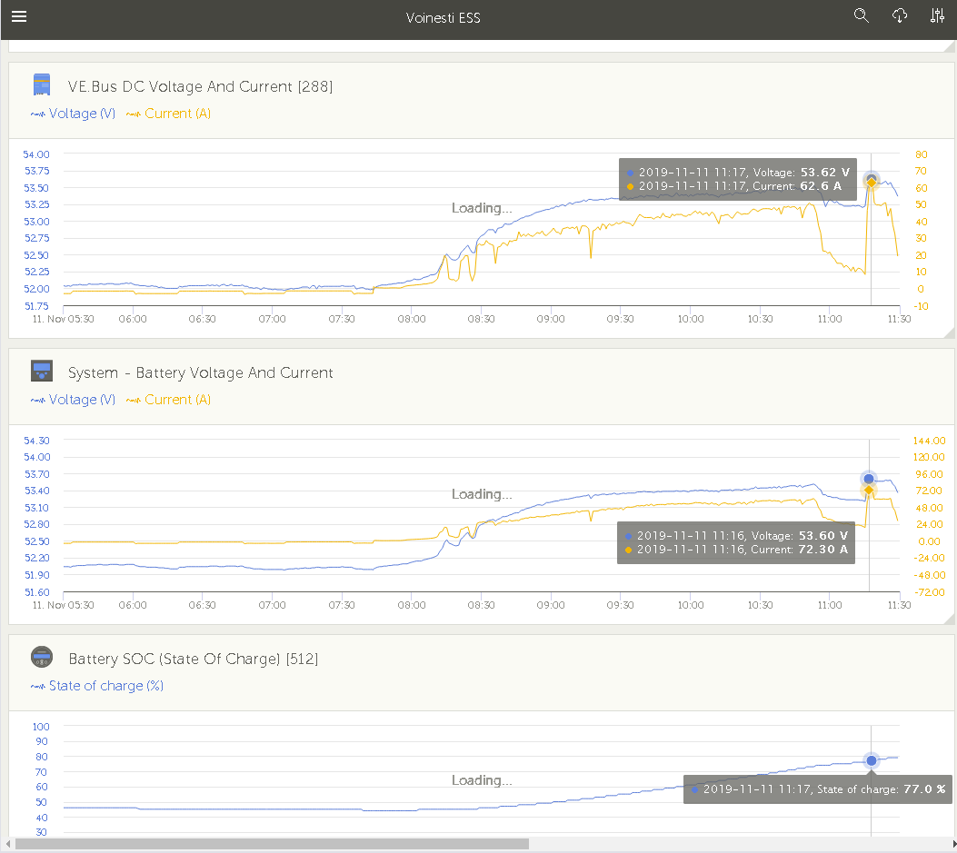
I would kindly ask the owners of 48/5000/70 Multis to confirm here if they ever seen charge currents over 50A in their systems.

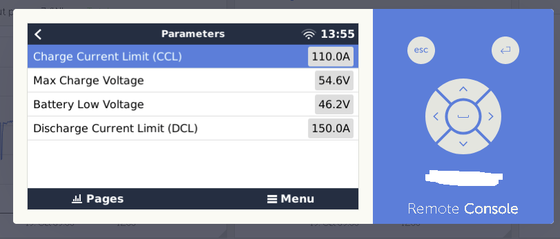
I have installed two identical ESS systems in last year and none of them were able to charge with more than 50A even the solar power was plenty enough, all excess power is dumped into the grid. The REC-BMS LFP battery BMS didn't limit the charge current at such a low value.

Please see the pics below for exemplification.


Thanks,

Mihai
MultiPlus Quattro Inverter Chargerbattery charging
rec-bms-param.png (46.1 KiB)
54ampmaxcharge.png (70.7 KiB)
2 |3000

Up to 8 attachments (including images) can be used with a maximum of 190.8 MiB each and 286.6 MiB total.

4 Answers
mihair avatar image
mihair answered ·

Hi Guy,


Problem solved. Has nothing to do with charger efficiency.

Into product documentation (manual) is stated that:


5.5.1.3 Battery charge current limitation (default setting 75%)

For maximum battery life, a charge current of 10% to 20% of the capacity in Ah should be applied.

Example: optimal charge current of a 24V/500Ah battery bank: 50A to 100A.

The temperature sensor supplied automatically adjusts the charge voltage to the battery temperature.

If faster charging – and a subsequent higher current – is required:

- The temperature sensor supplied should always be fitted, since fast charging can lead to a considerable temperature rise of the battery

bank. The charge voltage will be adapted to the higher temperature (i.e. lowered) by means of the temperature sensor.

- The bulk charge time will sometimes be so short that a fixed absorption time would be more satisfactory (‘fixed’ absorption time, see

ds5, step 2).

Procedure

The battery charge current can be set in four steps, using DIP switches ds4 and ds3 (default setting: 75%).

ds4 ds3

off off = 25%

off on = 50%

on off = 75%

on on = 100%

Note: when WeakAC is on, the maximum charge current is reduced from 100% to approximately 80%.


6 comments
2 |3000

Up to 8 attachments (including images) can be used with a maximum of 190.8 MiB each and 286.6 MiB total.

petajoule avatar image petajoule commented ·

I think the manual is very "Lead-ly" there.

0.5C charge for LiFePO is pretty ok, 0.3C is a walk in the park.

for a 500Ah LiFePO4 box 0.3C is ... wait ... sandclock turning ... 150A far beyond 5000VA device space and time.


1 Like 1 ·

Ah yes, step 1, read the manual :)

Have you since adjusted that setting and seen higher output?

0 Likes 0 ·
mihair avatar image mihair Guy Stewart (Victron Community Manager) ♦♦ commented ·

I didn't changed the switches yet but i'm 100% confident that product manual is right :-)

Don't you?

0 Likes 0 ·

I am curious to see how much real power difference it makes in this case.

0 Likes 0 ·
mihair avatar image mihair Guy Stewart (Victron Community Manager) ♦♦ commented ·

Hi Gui


Last weekend I modified the charger settings via the dip switch ds4 ds3, enabling 100% charger current.

I am very happy with the results, for the first time since commissioning my battery was peak charged with more than 70A.

Charger efficiency is more than 90%

Have a nice day,

Mihai

0 Likes 0 ·
100charger.png (57.6 KiB)
mr-manuel avatar image mr-manuel commented ·
@Guy Stewart (Victron Community Manager) is this also valid for the MultiPlus II?
0 Likes 0 ·
Guy Stewart (Victron Community Manager) avatar image
Guy Stewart (Victron Community Manager) answered ·

Hi MihaiR,

That would seem to be fairly normal, though I can have a closer look at your VRM info if you like.

The charger component of the Multi is not as efficient as the inverter part. I don't know precisely, but ~85% sounds about right.

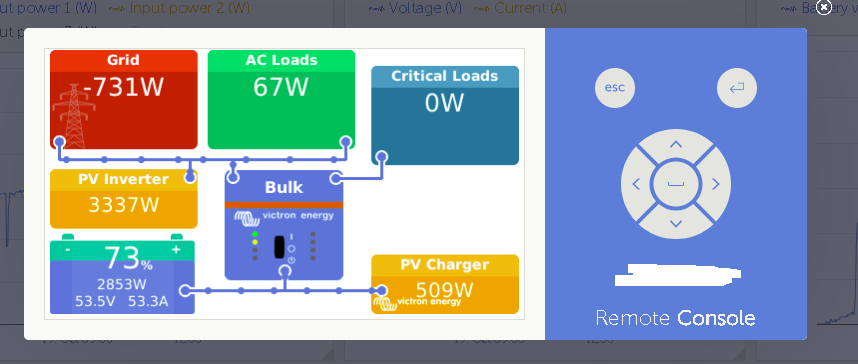
3337W of AC PV divided by 53.5V DC battery equals = 62.4A total potential

62.4A at 85% efficiency equals 53.04 charging amps.

In this case, there is an extra 500W of DC PV, and -700W of export, but I think if we look over more time and more data points, that it will work out pretty close to the same.

Generally speaking, DC MPPT's are a LOT more efficient at charging batteries than AC PV inverters connected to Inverter/Chargers.

4 comments
2 |3000

Up to 8 attachments (including images) can be used with a maximum of 190.8 MiB each and 286.6 MiB total.

mihair avatar image mihair commented ·

Hi Guy,


Thanks. What do you need in order to look at one of my system?

Where is stated that charger efficiency is 85%?


Thanks,

Mihai

0 Likes 0 ·
mihair avatar image mihair commented ·

https://www.victronenergy.ro/upload/documents/Output-rating-operating-temperature-and-efficiency.pdf

Seems that charger efficiency should be 100% at temperatures below 25 degree C.

My systems never exceed this point

0 Likes 0 ·
Show more comments

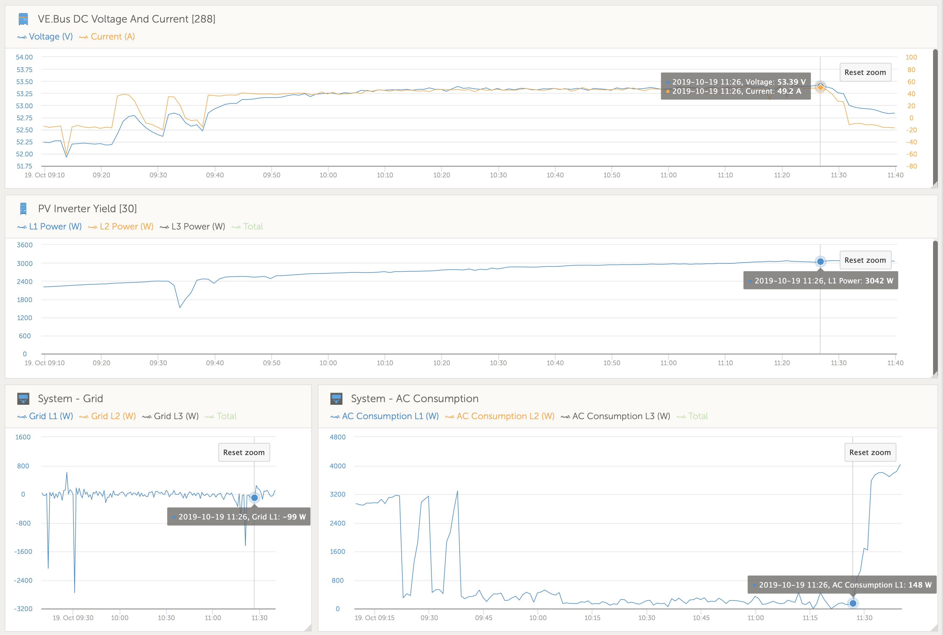
I found a good example in your VRM.

What makes it a good case is that it was a good sunny solar day, loads are not switching on and off, and batteries are not anywhere near full, grid export is ~ net 0, loads are very low ~100W.

All available AC PV is going to battery charging, and heat loss through efficiency.

This might not be the case at other times when there is fluctuating conditions, such as varying loads or passing clouds, that's ok too, and part of the design of ESS to allow a smoothing of the AC side of the system using the grid support.

alt text

0 Likes 0 ·
ac-pv-charging.jpg (673.5 KiB)
kolfleading avatar image
kolfleading answered ·

Maybe with a higher Absorbtion voltage, the battery would use a higher current?

Assuming 16S LFP, the 54.6 V setting works to a little over 3.4 volts/cell. And the SOC was already pretty high, at 73%. If we also consider voltage drops over the wires...

1 comment
2 |3000

Up to 8 attachments (including images) can be used with a maximum of 190.8 MiB each and 286.6 MiB total.

mihair avatar image mihair commented ·

The charging current is the same at 30% SOC as it is at 70% SOC. The absorption point was not reached in the presented images.

I am using low charging stop voltage per cell in order to extend the life of my batteries

0 Likes 0 ·
mihair avatar image
mihair answered ·

Hi,

Today I did another test in order to find if the upper charging current limit is reachable by modifying grid setpoint remotely with the following command:

#dbus -y com.victronenergy.settings /Settings/CGwacs/AcPowerSetPoint SetValue 5000

The grid setpoint was correctly set up to 5K but the charging current never exceed 60A. Why 70A max charging limit isn't reachable?

There is no charge current limit set up on CCGX/SytemSetup/DVCC and in VEconfigure/Charger/Charge Current 70 is set

There is any other related thresholds set up in other places than the above?


Thanks,

Mihai

2 |3000

Up to 8 attachments (including images) can be used with a maximum of 190.8 MiB each and 286.6 MiB total.