Hello fellow installers,
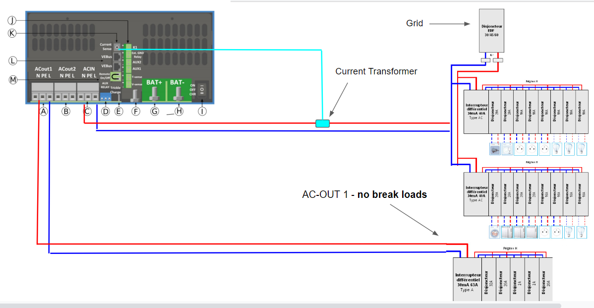
We're about to set up a DC coupled ESS comprised of a Multi 5 kVA and a MPPT 250/100. So far we've been wiring ESS with an in-line topology, which is pretty straightforward, but in parallel, we got confused by the external CT and the relevance of using the AC-OUT 2. We couldn't find neither any specific wiring schematics detailing the various possible configurations when using a parallel topology. Feed-in is not tolerated, and we need to proceed with parallel wiring of the system, as the subscribed grid power of the customer is at 65A (~ 15 kVA), higher than the internal relay of the Multi. The wiring diagram would looks like this :

Some remarks, for which we'd like to have confirmation from installer who have already installed ESS in parallel mode :
- First, the CT should be installed downstream, before the main switchboard, so that it can monitor the power drawed from the grid and thus prevent feed-in and matches the grid setpoint set in the GX, correct ? Problem is that it is rated for 32A max, if the loads draws more than that, the monitoring will not be precise and we need to use instead a ET112 @100A, correct ?
- Second, in normal operation, as the AC-IN line is bi-directionnal, all the switchboard will be energized both by the PV power from the DC bus from the Multi, AND the grid if needed right ? If the grid fails, only loads connected to ACOUT1 are still powered, correct ?
- In parallel topology, how we can use the AC-OUT 2 ? As all non critical loads are powered by AC-IN, what's the usefulness of having an AC OUT 2 which has no backup and which is limited to 32A ?
Thanks a lot folks !
