question

run-the-race avatar image
run-the-race asked

Struggling to connect 70mm2 lug to Battery Switch ON/OFF 275A

If I try connect the lug with the flat side of the lug facing down, then it cannot sit flust with the 1st nut (the 2nd nut tight the lug again the 1st nut)
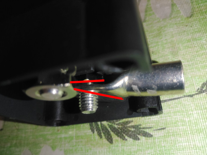
lug1.png

However if I try with the flat side of the lug facing up, then the lug sticks beyong the box and I cant mount it flush to a wall.
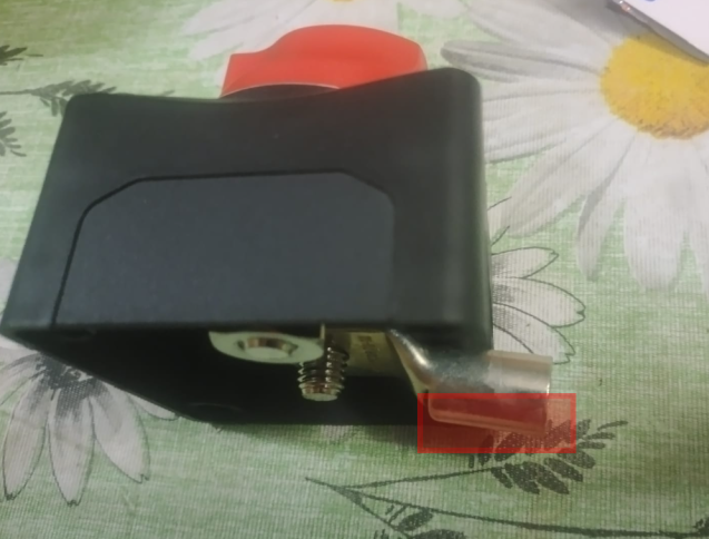
lug2.png

If I loosen the 1st nut out, so that the lug can sit flush against the nuts, then the thread bar jiggles and feels loose, and I fear the other side of the thread bar is not making contact with the switch internals. Is this okay or should it be avoided?
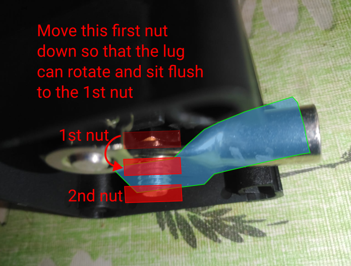
lug3.png

Thanks for any advice.

switch
lug1.png (398.2 KiB)
lug2.png (331.0 KiB)
lug3.png (395.0 KiB)
2 |3000

Up to 8 attachments (including images) can be used with a maximum of 190.8 MiB each and 286.6 MiB total.

3 Answers
klim8skeptic avatar image
klim8skeptic answered ·

@run_the_race the removable panel/blank in the middle photo looks large enough to allow cable/lug connection.

1 comment
2 |3000

Up to 8 attachments (including images) can be used with a maximum of 190.8 MiB each and 286.6 MiB total.

run-the-race avatar image run-the-race commented ·

Unfortunately the panels on all 4 sides are the same size.

0 Likes 0 ·
daza avatar image
daza answered ·

i wouldn’t lose that as that may well keep some of the internals at bay, you want these things to sit flush as this is a high resistance point all by itself having these not making good contact on the isolator isn’t going to help, just my 2 pence

2 |3000

Up to 8 attachments (including images) can be used with a maximum of 190.8 MiB each and 286.6 MiB total.

Craig Chamberlain avatar image
Craig Chamberlain answered ·

To be honest, these switches are pretty poor and if you ever switch them on or off under load then you will probably need to buy a new one because the arc caused by switching under load will make the contact resistance increase and they will heat up.

That all said, if you do decide to use this switch then it is ESSENTIAL that the bottom nut is snugged up against the plastic otherwise the contact surfaces inside the switch won’t sit flush and you’ll get a high resistance connection and potential fire. You can open up the switch carefully by removing the four screws and you’ll see what I mean. Just be very careful to reassemble it correctly.

I know what you mean about the lug not sitting flush but I have 70mm2 lugs on my switch and it just about screws flush to the wall. Maybe your lugs are different to mine though, I got mine from 12voltplanet.co.uk. What you might be able to do is put the flat part of the lugs in a vice with soft jaws and bend the lug slightly to make it exit the switch parallel to the wall. But just be very careful not to overdo it and make sure you don’t put a curve in the connection surface.

HTH

2 comments
2 |3000

Up to 8 attachments (including images) can be used with a maximum of 190.8 MiB each and 286.6 MiB total.

run-the-race avatar image run-the-race commented ·

Thanks for that detailed info very helpful, I opened up the switch and it was broken in side with all my fiddling trying to get it to fit. I hammered the lugs to change the angle of the cable and now it fits. I hope the cables did not work lose with the hammering, but they are covered with heat shrink, and still feel tight.

Ps On the packaging it says cranking current 1200A. And it still not okay for switching under load?I am probably going to be using like 80A max of the 275A rating. But I will try to not switch it under load, it's just an isolator from the 48V from the batteries to the inverter, and another one to the MPPT.

0 Likes 0 ·
Show more comments

Related Resources

Additional resources still need to be added for this topic